Whispering Skies Observatory: Installing Piers and Scopes!
Date: April 16, 2025

Getting to the “good stuff” on the observatory Project!
Table of Contents Show (Click on lines to navigate)
Earlier Posts in the Observatory Series
I have been thinking about building an observatory for a while now. Below are previous posts that have led up to where I am today.
Whispering Skies Observatory Update: Siding and Trim! March 2025
Whispering Skies Observatory: Developing a Computer and Networking Strategy! Jan 2025
Naming Your Observatory Jan 2025
Observatory Update: Powering Up the Observatory! Dec 2024
Observatory Update: Roughing In the Electric and Pouring the Slab Floor! Dec 2024
Observatory Update: Building the Structure! Nov 2024
Observatory Update: Laying the Foundation Nov 2024
Observatory Update: Custom Telescope Piers Part 3 - Painted and Complete! Sept 2024
Observatory Project: Breaking Ground! Excavation Complete! Sept 2024
Observatory Project: A Final Update Before We Break Ground! Aug 2024
Observatory Project: Opening The Roof! Aug 2024
Observatory Project: Final Roof Track System Hardware Selection July 2024
Observatory Project: Designing Custom Steel Piers - Part I June 2024
Observatory Project: Galvanic Corrosion and a Change in Track Selection! June 2024
Observatory Update: Designing the Roll-Off-Roof Track System! May 2024
The Move is Complete, Now Pivoting to the Observatory Project! April 2024
An Observatory Project Update: Success! We Just Bought A Property and Will Be Moving! Nov 2023
An Observatory Project Update - One Year In Feb 2023
Goals for my Observatory Project March 2022
Ready for Scopes!
Once the roof was motorized, I was basically ready to start setting up the piers and the telescopes!
The gaps that remained in the structure were not weather-sealed, but for some strange reason, I still did not get any weather coming in the exposed cracks over these past months, so I felt safe in proceeding!

Despite the fact that there were no weather seals installed around the wall/roof interfaces, no weather of any kind came in - despite heavy blowing snows and rain!
We were due to travel to North Carolina for a week and a half to visit my son's family there, and I was eager to get things going before the trip.
Video Companion
A video companion to this post can be seen on my Youtube channel:
Dressing Up the Pier Foundations
The pier foundations were separated and isolated from the slab floor, and this separation could look a little messy. So I excavated some gravel to ensure a clear separation between the two, and then stuffed in some closed-cell foam where I could fill the void.
I had an idea to use outdoor carpet to line the pier-pit depressions. Since each pier plate was in a slightly different position on the pier foundation, I needed to create a custom template for each pier.
To do this, I created four cardboard circles that fit the pier with a slot cut for the electrical conduit. I then pressed the cardboard down on the bolt pattern hard enough to make dents in the cardboard. Using these dents as a reference, I drew a circle larger than the pier plate and cut it out into four custom templates.

This is what the “Pier Pit” looled like once the sono tube was cut away. Not Very pretty!

Here is one cardboard template in place. Each pier needed it’s own template.
Next, I selected some outdoor carpet that was wide and long enough. I ended up ordering two 2x8 foot runners. I traced the template onto the back of the carpet and cut them out using some heavy shears. Then I cut strips wide enough to go around the inside circumference of the pits and cut those. I made those a little wide so I could adjust each one to what was needed. After all of the cutting this is what I had:
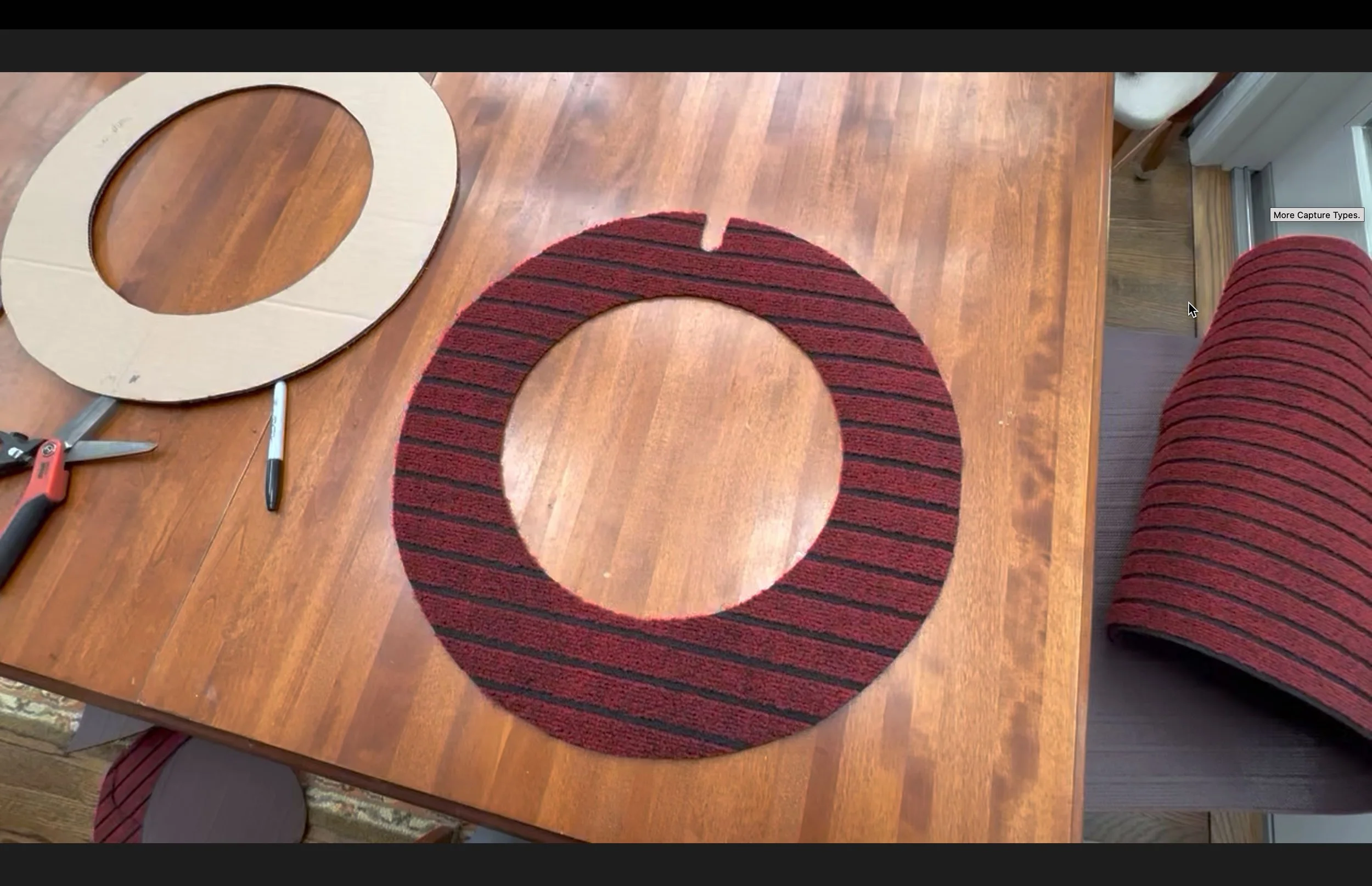
I used the template to cutout a ring of outdoor carpet for lay in the pit. I thought that the deep red would go well with the blue piers.
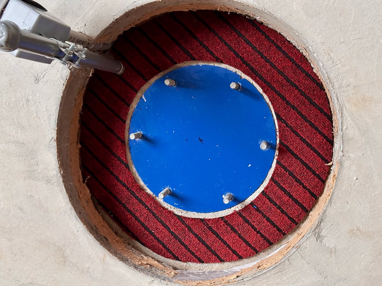
Ring in place…

A six inch border strip was rough cut for the sides.

It was too tall, so each strip was marked and trimmed.
The carpeting for the sides had to now be custom cut to fit each space. With my bad knees and back, it was hard for me to work that close to the ground so my wife graciously offered to help.
With the trimming done, the fit was great. The carpet is NOT glued down yet, as I need to remove it later when I put the epoxy finish on the floor. But even still, they look good and just sit in place nicely! Below is a shot with the piers in place.
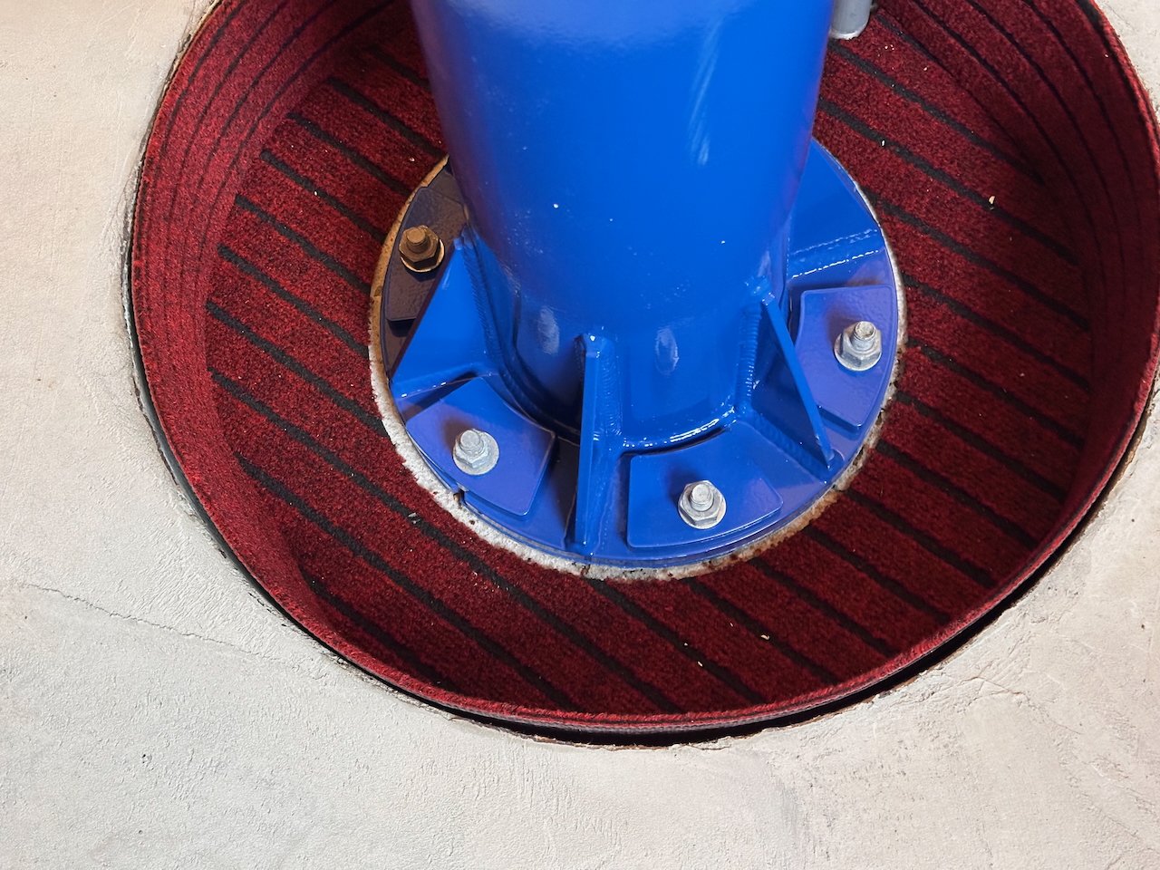
Here is one pit with the pier in place. The carpet is jus sitting there now. I need to remove it when expoxy the floor so for now it just resting in place.

Another finished pit sample.
Installing the Piers
The shots above show the piers in place. But how did they get there?
We had 10 inches of snow in the yard. Two inches down from the top was an ice layer. Problem? Not for me. I am strong like bull!
My wife has a great garden cart with a 1200 lb. capacity and 13-inch tires. I could load a pier into it and simply pull it up the hill—a piece of cake.!
The piers only weigh about 90 lbs. I can do this!
Well….
In reality, I barely got it into the cart.
Pulling the cart uphill was much harder than anticipated.
About a quarter of the way up the hill, the North side tires broke through the icy crust, and suddenly, I was pulling the card through snow and ice - up hill.
This was a real struggle! I was exhausted when I got to the top of the hill. Given that I had a heart attack 20 years ago, I am NOT supposed to be doing this kind of thing.
I don’t have a video of this effort. Thank God for small favors.
At the top of the hill at the observatory, I still had to lift the damn thing out the cart and get it into the observatory. I was exhausted, and to make things more interesting, it started snowing heavily again.
Somehow, I got the pier out of the cart and into the observatory. But there was NO way that I could carefully lift and set this thing down onto the bolts in the pier foundation. I was going to need some help.
So I went on our trip to North Carolina, and while there, I asked a couple of my astronomy friends if they would be willing to help the weekend after I got back. We tentatively planned to use a toboggan to get the remaining piers up to the observatory. I would also investigate some ways to apply strap handles to make it easier to grab onto and move.
After the NC trip, the designated weekend was approaching, and it worked out that the contractor was going to come back and work on the siding that Friday. They offered to move the piers up the hill for me! That was not their job, and I really appreciated the offer!
Friday came, and so did the contracting team.
I reminded them of the offer to move the piers, so they walked down the hill and into my garage. I was somewhat amazed to see two guys each slinging a pier on their shoulders and quickly walking up the hill like it was nothing. Once they got them in the observatory, each guy just gently lowered the piers onto their bolts—all by themselves. Another trip and all of the piers were in place!

Our construction crew making the transport of the piers look too easy!

Drop it on the bolts? No problem! No, I don’t need help…

Way too easy!

Piece of cake!
I was very appreciative.
I was impressed.
I was grateful.
I was pissed that they made it look so easy…
…It almost killed me to move one. They could have at least acted like they were struggling with the task. But, nooooo! I never felt so old before.

The four piers finally in place!
Adding the Pier Top Plates
The piers were now in place. They had not yet been bolted down, but they were all ready to go.
My weekend helpers would no longer have to strain so much to help me! Instead, we could focus on leveling the piers and then getting the mounts and scopes in place. I was sure they would be very disappointed to learn of this change.
To prepare for their help, I decided to mount the pier plate adapters onto the top of the piers themselves.
I had recently bought an IOptron CEM 70 for the SCA260 platform, so three of my piers would use a modified version of the Ioptron Top Pier Plate for the CEM60/70.

These had been previously bought for a very reasonable price and modified for use on my custom piers. I drilled out and countersunk the four holes in the plate pattern to be compatible with the holes/threads on the top of my pier.
Once this was done, I could mount the plates using four stainless steel bolts with conical heads and a star driving face. These were coated in wax lubricant and bolted to the piers.

The top of the pier. This is 1/2-inch plate steel tapped with 4 bolt holes.
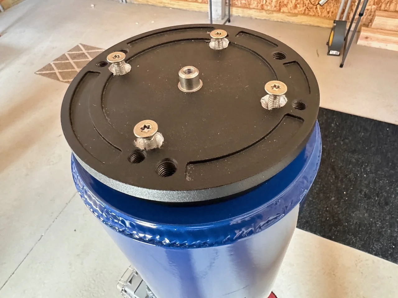
The bolts started on the Ioptron Top Pier Plate.

Each bolt is lubed do they don’t stick or bind over time.
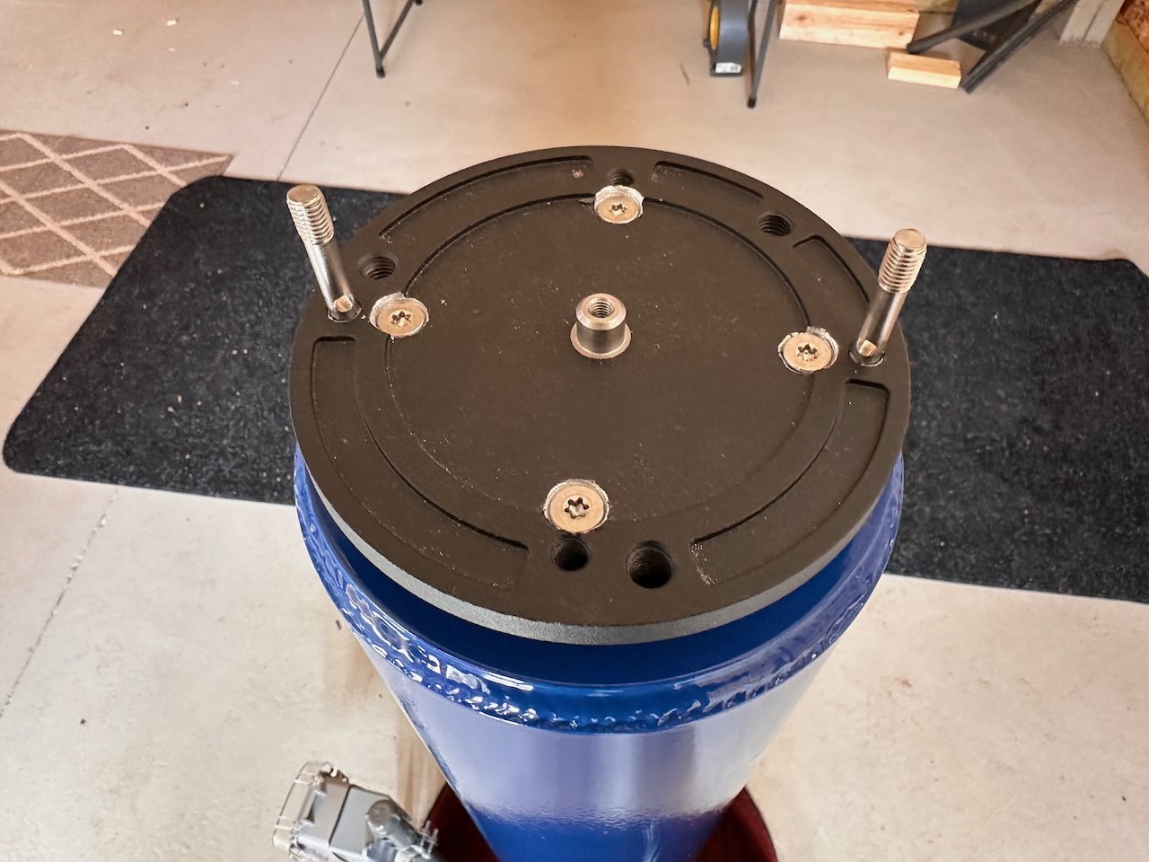
Bolts are now tightened and the mounting posts for the CEM60 installed.
The FRA400 platform, using the AM5 mount, just needed a standard 3/8 tripod bolt. I had created an adapter plate for this and it was quite simple to bolt this to the Pier. The Riser for this mount was used to attach to this.
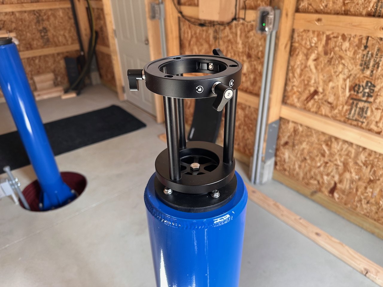
This is the extention for the AM5 mount. This is bolted to a custom plate with a threaded 3/8 tripod hole.
Leveling the Piers
My friend Gary had made some stainless steel shims so that we could adjust the piers before we bolted them down. I checked the level of the piers as they were just sitting there unbolted. Measuring at the top of the pier, they were pretty darn level. The worst one was off by 0.5 degrees, and the others were less than this.
So, on Saturday, Gary and Glenn came over at the appointed time, and we began to play with the shims.
It did not go well.
At one point, we put in a shim and tightened the bolts, only to find that the level was worse than when we started! We went to remove the shim and we just could not get at it unless we lifted the pier out of its well.
So we three old guys just managed to do this.
We found that the shim had slipped into the middle of the plate rather than staying at the edge. This was not helping at all.
We ended up bolting down each pier without shims and checked level. They were actually quite good once bolted down, so we left things alone.

The piers needed little leveling.
Bringing Up the Scopes
I had already torn down my scopes, so we needed to bring two larger OTAs up the hill, along with two Ioptron CEM60 mounts and their counterweights. The mounts and counterweights came up the hill in the cart. (The snow had melted at this point, so between that and the extra helping hands, this was simple.)
Two of us would carry each OTA up at a time.
The FRA400 was small enough that one person could carry the OTA and the mount as one unit.
We got them to the observatory and were ready to mount them. But what telescope should go to which pier?
I had already given this some thought.
One of the things that drove this decision was the need for a flat expanse of wall where I could mount a large Flat Panel light source for the Flat Calibrations for my SCA260 V2. I don't need this for my other scopes (either they have their own units, or I will be adding a closing telescope flap with a flat panel integrated—the SCA260 is too big for this).
The North piers can't use the N wall for this as cabinets will be there someday,
The NE pier has Roof Control Modules in the way
The NW pier could mount a panel on the W wall.
The South Piers can't use the south walls as they have windows.
The SE Pier has the electrical panel on the E wall.
The SW pier can use the W wall for this.
I can place the SCA260 V2 on the NE or SE Pier and use the West wall for a panel, but which one is better?
In general, I would say that there are a LOT of targets located towards the southern sky. So, if I put the smaller scopes on the South Piers, the Longer/Taller scopes can easily look over them so that I don't have the shadow of one scope in the field of view of the others.
So that is what I did:
The FRA400 platform is on the SE Pier
The SCA260 V2 platform is on the SW Pier
The WO132 Platform is on the NE Pier
The Astro-Physics 130 platform is on the NW Pier.
I had brought my Astro cart up to the observatory.
I used this as a place for two control laptops when I was shooting from my driveway. Now, I can use it to wheel things around the observatory, like heavy OTAs or mounts and their counterweights. We used this to hold the heavy CEM 60 mount heads.
Soon, my existing scopes were mounted with the help of Gary and Glenn. (Thanks, Guys - I really appreciated the help!)
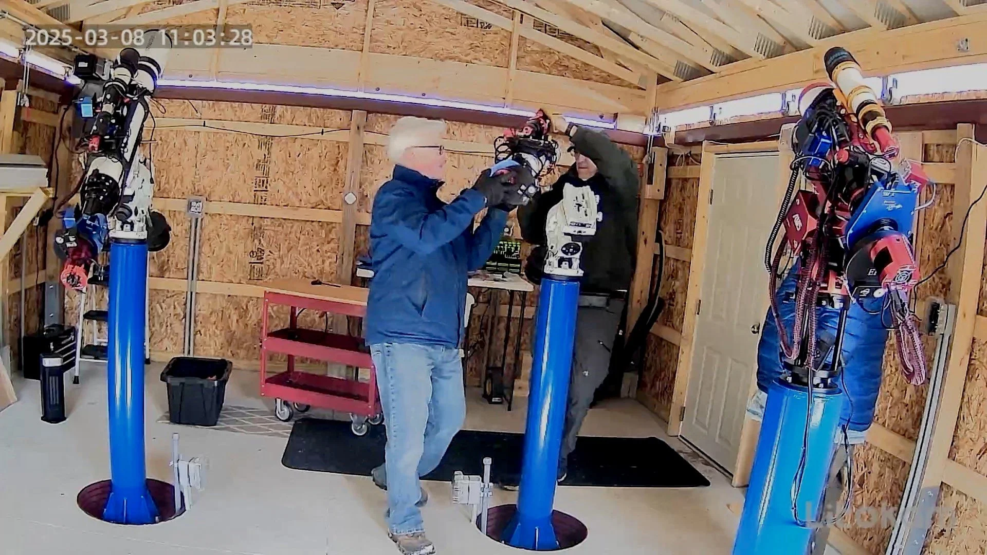
We were too busy working on the scopes to video or photograph the action here, but later, I realized that my Observatory Security Camera probably got some shots as they were in tracking mode. So I pulled off a few stills of the action. Quality is a little crude due to the image source, but it gives you a flavor of what went on!

Security camera snap of us installing one of the CEM60 mounts.

Now, the Astro-Physics 130mm OTA is being installed. Note the red astro cart - super handy to have!
The William Optics 132mm OTA being installed.

Finally, putting in the FRA400 Platform.

3 out of 4 piers populated!
The 4th Pier
While I had the telescope for the 4th pier, I did not yet have the mount.
I was planning on buying the mount later in the year, but given the current tariff nonsense, my wife and I decided to buy it now before prices go up.
So, I ordered an Ioptron CEM70 mount.
While I will have a dedicated video on setting up and configuring the SCA2260 platform, I will share here that with the arrival of the mount, I was able to get the SCA260 set up on the 4th Pier.
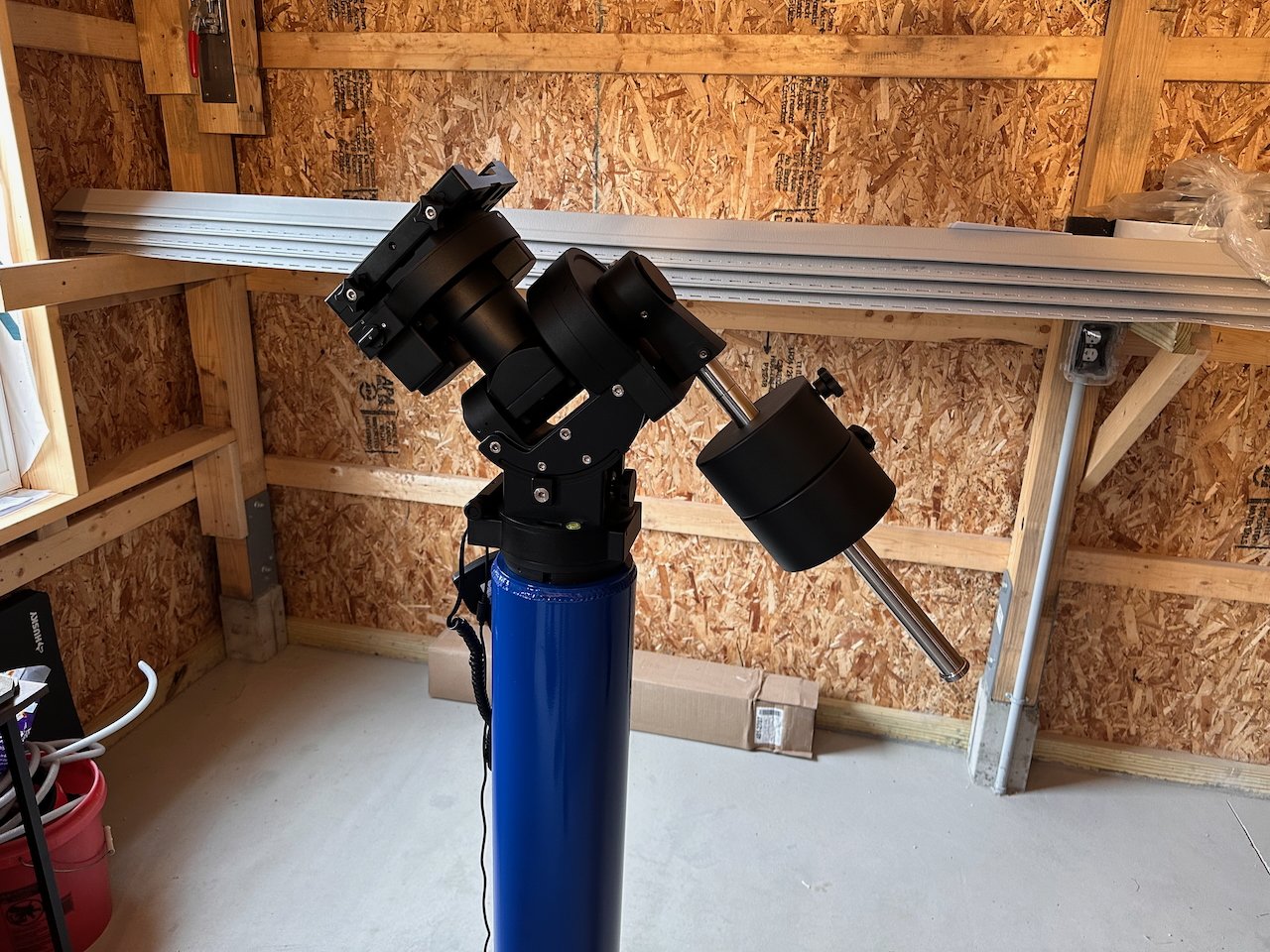
The CEM70 mount, newly installed!
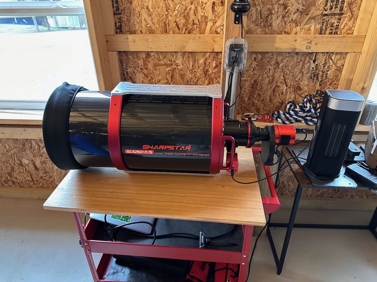
Getting the Sharpstar 260 V2 OTA ready…

Mounted!
I also mounted an old ASI1600 camera that I had on it so that I could do a few things with it.
Power and Computers
The scopes on their piers look great, but they don't function.
I needed to get some power and computers set up for each one.
I used Gel Tape to mount the Mele Quieter 4C computers on the Piers temporarily.
I then used a 1.5-foot pigtail and a 3-way outlet splitter to bring power from the box. I mounted two Govee WiFi Smart Switches to this. On one of these, I plugged in the power supply to the mini PC. With the other, I ran power to the telescope OTA assembly. With this arrangement, I can remotely power cycle the computer or the scope and all of its equipment.

The initial power cable bundle. A rat’s nest!

All of them were pretty bad at first!
This left a table of wires handing out that would not be protected from dew. I purchased four gray waterproof utility boxes to house these and then cleaned up the cable situation using magnetic cable guides.

These waterproof boxes would help!
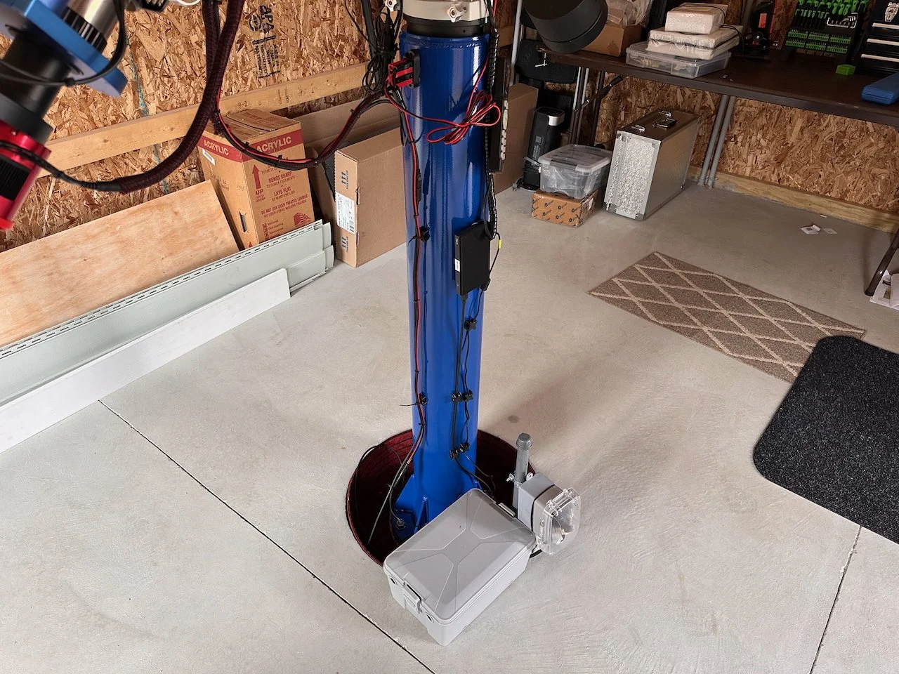
Final Arrangement.

All piers mounted, power and computers in place.
The computers had already been configured with NINA and all other needed software.
Getting the Equipment Connected to NINA
My plan has been to migrate all of my telescopes over to NINA. I had crossed my FRA400 platform (as run on my laptop) over in the past year and really loved the NINA system.
I took the new MicroPCs and set them up as I documented in a previous post (that you can see HERE). Then, based on my laptop experience, I started setting up NINA on each PC.
So it was reasonably easy to get things started with each telescope. Basically I connected all of the devices to the NINA profile and then started by taking images with the main camera in a loop.
This allowed me to focus the cameras manually.
Then I got the Autofocus routines working using methods as described by Patriot Astro , which you can see HERE.)
Now that I can take images, I set up and I tested Platesolving. (I am using ASTAP, which I had already set up on each PC)
This was pretty straightforward, and I ran into no issues up until this point. (However, that was about to change!)
Now I was ready to do my first Polar Alignments.
The First Major Screw Up
I was obsessed with the thousands of details on this observatory project. Probably the thing that I was most concerned about was the angle of view.
How low you can see in the sky depends on several factors:
Height of the center of the telescope tube
Height of the wall
Thickness of the wall
Distance from the pier to the wall
Trees in the area
I generated a spreadsheet where I explored these parameters in detail. Trickier yet was figuring out the view angle to the north. I wanted the scopes to see past the roof and be able to see Polaris for Polar Alignment. I use PA Cameras for alignment, so this was critical. I had to play with this one a bit due to the shape of the root.
I had to consider:
The height of the peak of the roof
The location of the roof relative to the piers when in its final open position.
The height of the roof from each pier position, as I was sighting over the slope of the roof.
The impact of the trees towards the north.
I really wanted to ensure I had reasonable sight lines in all directions and that my scope could see Polaris for PA.
When I determined the observatory's location on the hill, I verified that each pier position could see Polaris over the trees in that direction. This was a relief.
I ensured each critical dimension was achieved correctly when we built the observatory.
We ran into one error when we installed the roof drive. In order to get the clearances we needed for the motor, the roof ended up opening about 6 inches further south than initially intended. Oops.
Then, when we had the first clear night after the telescopes were installed, I tested whether the northernmost scopes could see Polaris in their field of view…
Yes, they could! Success!
Pat, you mastermind, you made it all come together without a hitch!
Now - time to use iPolar and Polemaster to do the PA's.
I fired up the cameras and ---- saw NO stars at all - just the face of the roof gable! WHAT????????
So, genius-boy Pat did all of his calculations on the center of the telescope tube. The iPolar and PoleMaster scopes, however, are mounted on the RA axis - which is located almost a foot below the telescope optical axis.
DOH! ( Major head-slap),

The PoleMaster PA camera is mounted much lower than the optical tube. Doh!
My Northernmost PA Cameras Would Never See Polaris Again!
I dined on a menu of panic and self-recrimination, with a side of despair…
Then, I had a thought: DRIFT ALIGNMENT.
Yes, that would work. PHD2 offers this PA method, and I have used it before when I was operating remotely and could not see Polaris from my location.
Then I had a second thought: NINA has a 3-Point Polar Alignment plug-in that I heard people rave about.
It was time to check that out!
3-Point Polar Alignment
Long story Short: I used the 3 Point Plugin to do Polar alignments for those scopes.
It was easy to use. I connected to the MiniPC using the Windows Remote Desktop Client from the main Observatory Control computer. With its relatively large screen, I could read the needed adjustments while standing next to the scope, making the Alt/Az adjustments as needed.
The image below was taken from my security camera in IR mode, as I did this.

Infrared security camera view of me using the NINA 3-point PA Plugin to align the mount.

Here is where I ended up with the AP130 Platform PA adjustment using the 3 point PA plugin.

And here is the WO132 platform results.

I ended up running this for the Southern Pier Scopes as well. Here is the FRA400 results.
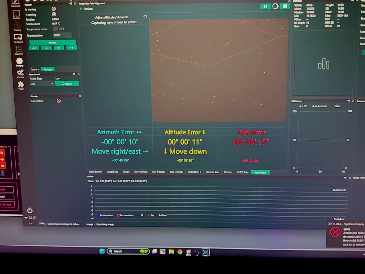
And finally - the SCA260.
Time and my first guiding session will tell me if it is actually as good as it says it is, but I am at this point, very relieved!
Moral to the Story - When you are working on a plan for an observatory, double and triple-check everything. After the build, it is a really bad time to find something that is not working out. For myself, the fact that I did not take into account the offset between the center of the telescope tube and the location of the PA camera was a major major brain fart.
I think it is sometime good to be humble by random acts of personal stupidity. It keeps our head from getting too large and our egos in check!
Current Status
For the most part, everything is ready to go. I am still fighting some auto-focus funkiness on my FRA400 platform, and the SCA260 still needs the final setup (the ASI2600MM-Pro, the EFW, and the filters for this scope are due to be delivered today!) and a final collimation check.
But if we get a good, clear night, I am ready to catch photons.
Stay tuned!!