
Observatory Project: Designing Custom Steel Piers - Part I
Date: June 29 , 2024

Table of Contents Show (Click on lines to navigate)
NOTICE!
This post shares my preliminary design thoughts for a Roll-Off-Roof Observatory.
I make NO representations regarding the fitness or soundness of the designs and design decisions discussed.
Use this information at YOUR OWN RISK!
If you decide to build your own version of this project, you ASSUME ALL LIABILITY for your efforts and their results.
Earlier Posts in this Series
I have been thinking about building an observatory for a while now. Below are previous posts that led me to where I am today.
Observatory Project: Galvanic Corrosion and a Change in Track Selection! June 2024
Observatory Update: Designing the Roll-Off-Roof Track System! May 2024
The Move is Complete, Now Pivoting to the Observatory Project! April 2024
An Observatory Project Update: Success! We Just Bought A Property and Will Be Moving! Nov 2023
An Observatory Project Update - One Year In Feb 2023
Goals for my Observatory Project March 2022
The Video Companion to this Blog:
The Start - Concrete Piers
As I have stated before, my observatory design was inspired by the West Texas Observatory. In that project, they created four concrete piers. Since I wanted to have four piers as well, it was only natural that I would do the same.
Concrete is solid, and the piers could be fabricated with simple tools: a Sono tube, rebar, a J-bar holding plate, and concrete. Since concrete was needed for the foundations, pouring the piers would not be a big deal.
So the initial design was for a 10 or 12 inch concrete pier with 4 bolts coming up from the surface.

Draft design for concrete piers

West Texas Observatory - showing the slab floor and the concrete piers.
A Change in Direction
My wife raised a concern once we bought the property and started actively considering getting the observatory project off the ground.
“What happens with the observatory when we move someday?”
Well, the chances are slim that the new buyers would want an observatory, so I floated the idea that we could position it as a storage shed. I could clamp down the roof. Of course, the problem with this is that the heart of the “shed” would have four massive concrete piers blocking the way, so this was a concern.
The next concern was the cost. Since pre-COVID, the cost of concrete has gone through the roof. So, the cost savings between this and commercially available steel piers were smaller than before.
Finally, I wondered if the 10 —or 12-inch-diameter pier might sometimes get in the way.
My two large scopes had a 6-inch pier that allowed them to move freely. However, the wider pier might catch parts of the scope, and that would certainly not be a good thing.
I started playing with the idea of using steel or aluminum piers.
I could put in the pier foundation and have bolts below the level of the observatory floor. Then, the piers would bolt in. If we ever had to move, I could remove the piers and put a cover plate over where they were, and now I had a nice, even, large space that could be used as a shed.
This was likely to cost more, as I had to buy prefabricated piers, but my wife thought the extra cost would be worth it.
So, I started researching commercially available piers - A few samples can be seen below.

Primaluelabs C82 Pier

IOptron Permanent Pier

Pier-Tech - Double-beam Stationary Pier
To Buy…. Or Build…
As I researched commercially available piers, I saw a few things I did not like:
Cost - Some of these piers could get quite pricey, especially if you are ordering four of them!
Availability - some were in stock, but most had relatively long order times.
Physical Configuration—Most were sold in a specific configuration, with a fixed diameter and height, and they were not what I wanted or needed.
This was frustrating as I have zero ability to build one myself!
I have had very good success with my current gear setup. I have set up the IOptron CEM60 mounts, so they work very well with the IOptron Tri-Piers, which have a roughly 6-inch diameter. I would like to have a pier that offers a similar configuration.


As I talked to various friends about this, one friend in particular I knew had built his own heavy-duty pier for his massive observatory build.
Gary Villa was an old friend from college that I was happy to reconnect with a few years back when he built his own observatory and stumbled across my website. He contacted me through the website, and it was great to hear from him!
When he showed me the observatory he had built for himself, I was astounded. It was amazingly well thought out and constructed, and I was (and continue to be) amazed at what he had created. As part of this, he had built a very heavy-duty custom pier. As you can see below, Gary thinks big and plays big. His pier weighs in at 300 lbs!

Gary’s custom heavy-duty peir!
He did this because he is a pretty smart guy and owns a business that laser cuts materials, including steel!
He could order the metal needed from his suppliers and cut the steel, and he had a network of vendors who could weld things up, sandblast them, and do the final paint job.
Gary then suggested that he would help me create the piers that I wanted to have.
I have to tell you, I was floored by his very generous offer of help. I have no means or capability of doing this on my own, and to have an offer of assistance on this was not just enabling; it was a near miracle!
The next challenge was designing the pier.
Here, I had another ace in the hole—my mechanical engineering friend, Rick Albrecht.
Rick has been a great friend and a huge help to me for years and was willing to offer his skills and experience again to help me design the piers.
I can’t tell you how touched and grateful I am for the help of these two generous souls. I will have to find a way to repay their generosity.
The initial Design
I started talking with Rick, and we kicked around some preliminary thoughts:
My IOptron Tri-Pier was nominally 6 inches in diameter, so we started there. Let’s try to get something like a 6-inch diameter 1/4-inch thick steel pipe.
Building off my Tri-Pier, I wanted it to be 47” off the floor, so we needed this height.
Assuming the pier foundation was 4 inches below the concrete slab floor level, we needed the pier to be 51 inches high.
For the base flange, we would use 9-inch diameter 1/2-inch steel with holes for four j-bolts.
The top would be a 1/4-inch steel plate with holes, allowing me to bolt in an IOPtron Top Plate for the CEM60.
Material Availability and Refinements
With these rough ideas, Gary started to look at what metal he could source.
Half-inch Steel plate was no problem, and he found that he could source 6 5/8 inch steel pipe with a wall thickness of 0.28 inches. This could be bought in 21-foot lengths for a reasonable price, and the vendor would cut them to the sizes we wanted.
This was great, and the larger diameter and the thicker walls would make them stiffer and stronger.
So then I raised some questions.
How would we level the pier?
We should be able to laser-level the mount during the foundation pour.
Some minimal shimming could be done at the foundation level or the top plate if needed.
How would we ensure I could rotate the pier sufficiently to allow for Polar Alignment?
We had a long discussion about this, and it ended up bringing about a change in design:
We would add a steel ring to the foundation. This would act as a rotating surface that would hold the j-bolts in position.
The bottom flange would be wider (now 12 inches) and would now have six bolts, and the bolt holes on the flange would be curved and elongated such to allow rotation of the entire pier to facilitate the initial polar alignment
We would put six gussets at the flange to reinforce the base of the pier
we would cut large wedge-shaped washer plates to go on top.
The top of the pier would be 1/2-inch steel plate.

Bottom foundation plate is on the right, and the bottom flange of the pier is on the left. (Curtesy of Rick ALbrecht)
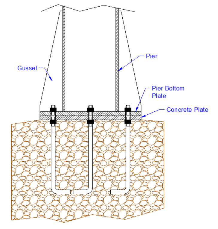
Here is what the assembly would look like. (Curtesy of Rick Albrecht)
How would I handle arbitrary mount needs in the future?
I could easily buy IOptron Top Pier Plates that were compatible with the CEM60 mount. These could be bolted to the top of the pier through the central four holes. This then would handle the two CEM60 mounts and the CEM26 mount, as there is an adapter plate that converts it to the CEM60.
The AM5 uses a 3/8-inch trop thread, and we could have a plate that bolts to the top of the pier. I was thinking of using the extender - this would allow me to bolt the extender to the circular top plate by threading a 3/8-inch bolts down through the extender cage onto the adapter plate.

Here is the IOptron Top Pier Plate for the CEM60. The red holes will be drilled out and countersunk so that I can bolt it to the top of the pier using four 1/4-20 bolts

These holes have been drilled out to 1/4 inch hole and countersunk to support flat top bolts for mounting.

Here are the flat top bolts in place. These are phillips head bolts, but I want to replae thise with Tox head bolts.
Would we want to fill the pier with sand for greater dampening?
We added a hole at the top of the pier to allow for this if desired.
The Final Design
With some refinements, Rick was able to create some CAD drawings of what we were proposing to build. These are a work of art themselves! I wish I had the skill to create files like these myself!
Here are some of those drawings.
Note: the dimensions are for my specific situation, and you may need different dimensions for your project!
his is the bottom ring, which will hold the six 1/2-inch J-bolts.

Here is the bottom flange of the Pier.

Here is the wedge-shaped “washer” plate:

And the top plate:

Finally - here is the whole Pier showing the pieces together.

Gary took these diagrams and had a 3D CAD diagram created that will be used for estimates and final fabrication. I created a short video viewing this file to give you a better feel for what it looks like in #D:
A 3D Rendering of the design
Getting Quotes
With this design in hand, Gary estimated the cost of materials and got quotes from the welder, the sandblaster, and the painter. The cost was very reasonable, and it looked like the project could be done in about eight weeks, which jives well with my timetable.
With this in hand, I pulled the trigger on the project.
The Next Installment
The next installment will cover the cutting of the parts from 1/4-inch and 1/2-inch plate steel.
I gotta tell you, Luke Skywalker has nothing over the lightsaber skills I saw at work when cutting this steel!
This work has already been completed, and I will create a blog post about it very soon, so stay tuned!