
Observatory Update: Designing the Roll-Off-Roof Track System!
Date: May 29, 2024

Table of Contents Show (Click on lines to navigate)
NOTICE!
This post shares my preliminary design thoughts for a Roll-Off-Roof Observatory.
I make NO representations regarding the fitness or soundness of the designs and design decisions discussed.
Use this information at YOUR OWN RISK!
If you decide to build your own version of this project, you ASSUME ALL LIABILITY for your efforts and their results.
Earlier Posts in this Series
I have been thinking about building an observatory for a while now - below are previous posts leading up to where I am today.
The Move is Complete, Now Pivoting to the Observatory Project! April 2024
An Observatory Project Update: Success! We Just Bought A Property and Will Be Moving! Nov 2023
An Observatory Project Update - One Year In Feb 2023
Goals for my Observatory Project March 2022
Here is the Video Companion to this post
Making the Roof Move!
When I engaged the first architect to draft the plans for my observatory, he was happy to do so with one proviso—he would not design the track system as he had no experience with such designs.
So, the track system was on me.
I was not too worried about this. There is a ton of information on the internet, and I have a talented mechanical engineer friend who is experienced in telescope and observatory design. I would work this out one way or another.
There are a few critical factors to consider…
The Weight of the Roof
One of the things I needed to know was the estimated weight of the roof as it was designed. The architect calculated this, and it came in at a surprising (to me) 7,000 lbs!
The roof was designed to consist of simple metal panels with no substrate - why so heavy?
There are two driving forces:
The roof is 16’ x 20’ - so it is pretty large
I used scissor trusses to maximize headroom, and these can be heavy.
What about snow loads?
The design has to handle typical static snow loads, but I do not plan on opening or closing the roof with snow on it.
We rarely get clear nights during winter
if we do, I will sweep snow off the roof before opening
So I need the track system to deal with a 7,000-lb roof. Just to be safe, I will be using 10,000 lbs when choosing components
The Track Foundation
The track will be located on the top plate of the East and West walls. The plans currently call for a cap plate consisting of two 2x6 sections of framing lumber.
This plate will continue along the tops of the East and West walls and towards the length of the outrigger framework.
So nominally, we are talking about 5.5” x 40’
Track Philosophy
Based on my friend Rick Albrecht’s suggestion, I am going with one side of the track using V-wheels and V-track and the other using flat wheels and a flat track.
If both sides were V-track, the design would be overly constrained, and the system could bind as the structure settles and weathers.

Rick’s Diagram illustrating the potential issue with over contrained designs.
V-Wheel and Track
As I shared in the previous post, I will be using the following V-wheels:

This wheel is 7.25” tall and 4” wide and can handle a 1000 lbs load. They run for $63 each.
If I mount 5 of them on one side, this alone would handle 5000 lbs of roof load.
I’m going to get 6 of them in case I ever need a replacement.
For the V-Track, I think I am going with the following:

From Amazon’s Web site.
This is an aluminum track, so I won’t have to worry about corrosion. With the central support, it should handle the loads fine. This is sold in 12’ sections, so I will need to purchase 4 of them for full coverage. This will also give me extra should I ever need it.
Flat Wheels and Track
For the Flat wheels, as I have shared in the past, I think I am going with the following:
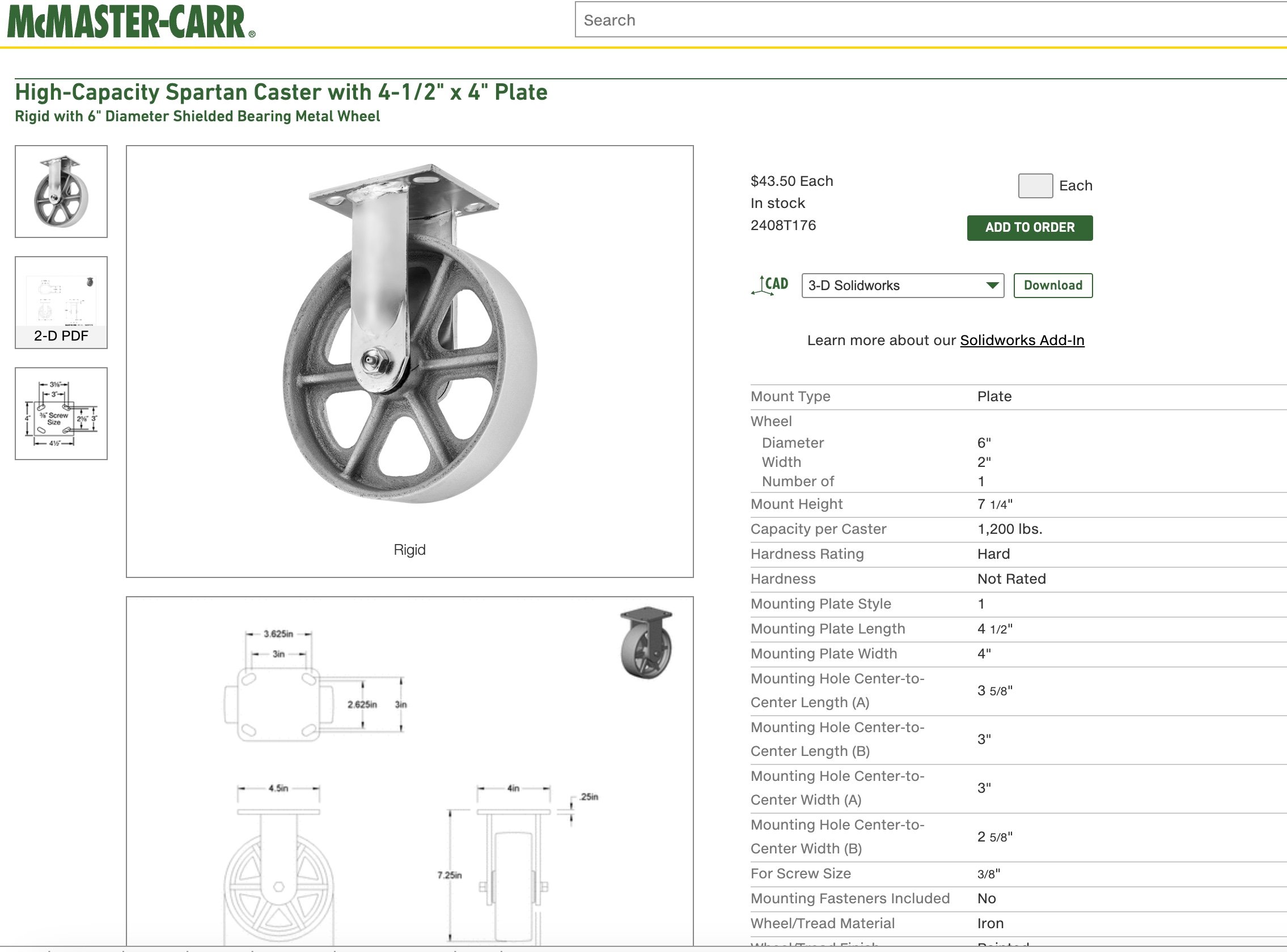
From McMaster-Carr’s Web site.
This wheel is 7.25” high and 4 inches wide. The same as the V-Wheel. It can handle a 1,200-lb load and goes for $43 each. Again, I will get 6 of them, and I am planning on using five of them on the track and one backup.
With this combination, I should be able to handle an 11,000 lb load, which should work fine.
For the flat track, I will use the following:
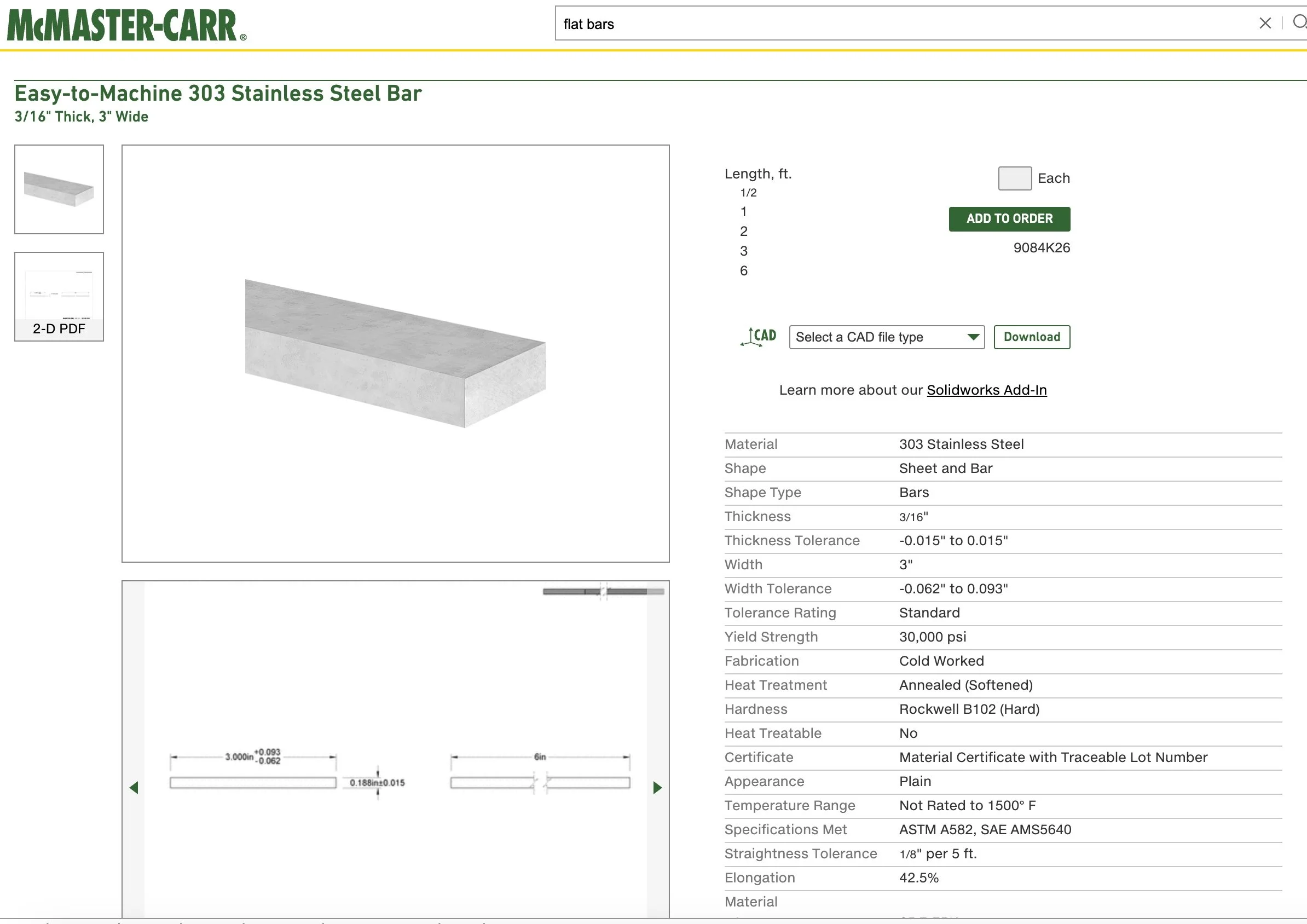
From McMaster-Carr’s Web site.
This is 3/8” Aluminum, 3” wide, and comes in 6-foot lengths for $72 each. I will need five of these.
The wheel's width is 2 inches, so a 3-inch track should allow for some buffer in the dimensional constraints.
Previously, I was going to go with stainless steel - but this raised the cost quite a bit, so I think I will go this way. I needed either aluminum or stainless steel, as the track would be exposed to the elements on the outriggers, and I didn’t want to worry about corrosion.
A few other points….
Self-Clearing Track
While V-track tends to self-clear snow or debris, this is not true for the flat track. This implies that I will need a system to clear the track as the roof opens.
I imagine mounting a kind of “snow plow” to the North side of the roof so that as it opens, it will self-clear.
Are the Tracks Level?
Another factor is that while the V-wheel and the Flat Wheel are the same height, the track is not the same thickness, and the V-wheel will sit differently than the flat track. This could cause the roof not to be level.
While this is true, it is not by much - 1/8 of an inch or so. At these scales, I don’t think it will matter.
Side Rails or Guard Rails
The V-wheels ride on the track formed by the “v” and will not “wander.” The flat track can wander a bit as there are no guides - and this is by design. On the other hand, you would not want to allow the “wonder” to be such that it could cause the roof to wander off the walls!
This is not likely to happen, but to prevent it, I think it would make sense to mount some “guard rails” on either side of the flat track. These could be as simple as 1-inch-wide strips of hardwood.
The guard rail locations can be seen here on the blueprint:

Location of the “Guard Rails”
Track Stops
Once the roof has a track system, it can move.
Of course, moving off either end of the track would be a very bad thing. It might completely wreck my day.
Since I hate having my day wrecked, we need to place stops at the front and the back of the track. These can be simple iron pieces preventing the roof from moving beyond the open and closed positional extremes.

Outrigger Track Stop location

Main Building Stop Location
Manual Roof Interlocks
Once the roof is closed, I must have a way to manually lock the roof to the frame. This will secure the roof from winds that could pull the roof from the building.
It would be manually engaged and strong enough to handle wind loads.
The architect shows this in the plan - but without getting into specifics:

Rick Abrecht suggested I use the following with a custom rod:

Rick Albrecht’s concept of a lockdown. This makes a lot of sense to me!
Another possibility is based is something I saw from Amazon:'

From Amazon’s Web Site.
This would handle 7700 lbs each! But I would have to elongate the U-bar on the latch to reach far enough
Stay tuned as I work this out.
Passive Roof Interlocks
My goal for this observatory is to automate it.
I want to be able to operate it from within my house. That gets a little hard if you only use manual lockdowns for the roof.
This implies that you need to physically go out to the observatory and unlatch the roof each time you want to open it.
It also implies that you must physically re-latch the roof once it has been closed.
Maybe I could manage that for the start or end of a session. But what I would like to do is to have the roof close on its own should clouds or weather move in. I would like this to happen while I sleep.
Why? Well, I am getting old and lazy, and I need my beauty rest.
It probably would not work that way. I would probably have my observatory wake me if it saw clouds moving in or the wind speed coming up - but as I default - I want it also to take a default action of closing the observatory.
One of the things I need is Passive Roof Interlocks. In this case, opening or closing the roof causes some part of the roof to engage with some part of the main structure, thus locking the roof down.
As I discussed this early on with Rick, he created a simple conceptual diagram.

Rick’s concept diagram for passive interlocks.
So, this was the concept - but how do we implement this? I needed something simple, light and robust. After looking at a lot of ideas and running this by Rick again, we settled on the pin/hole arrangement.
The idea here was to have a “pin” that consists of a 1” bolt coming through the wall at strategic places on the North and South sides of the observatory. The roof would have steel plates with a 1” hole in it. When the roof closes the plate engages the pin.
RIck came up with this design:

Rick’s design for a passive interlock using a 1” bolt as the pin.
With this concept, a 1” bolt goes through the wall with 4” diameter reinforcing plates on both sides. On the thread side of the bolt, we use a long coupling nut.
This secures the bolt to the wall and covers the threads so that the smoother metal of the coupling is exposed. The steel roof plate is secured to the moving roof section such that when the roof is closed, the plate is positioned over the bolt.
This is a simple design that could be used when the roof is in both the closed and open position.
Our current thinking is that three of these could be placed on the south side of the roof (both ends and the middle) and the north side.
It could also be positioned on the outrigger to do a similar task when the roof is completely open.
I really like this idea. Some details will need to be worked out, such as how exactly this will be positioned on the roof and walls. Since I will be having the walls redesigned to move from traditional stick framing to pole-barn construction, I will need to work this out later.
But this is the working concept for now.
The Roof Opening System
In a previous post, I shared a gate motor I thought I could use to move the roof. It seemed the right size and capability, and it even had a WiFi module for computer control.
However, it did not have software to control the roof nor an ASCOM driver to integrate with other devices.
I remembered that the East Texas Observatory group had used the Skyroof System by InteractiveAstronomy.
https://interactiveastronomy.com/index.html
So I looked up their website and found that they sold a roof control system that used a very similar gate motor and also sold a control subsystem that would work with other motors. This sounded interesting, so I wrote a note to InteractiveAstronomy to confirm their control system would work with the gate motor I was considering.
I got a call from Jim Collins from InteractiveAstronomy, and we had a long conversation about roof opening systems. Here is what I learned from that conversation:
The Skyroof system will not work with other gate motors because they found that the electronics controlling them could be triggered by electrical storms, causing unintended roof openings! Instead, they sell a modified version of the gate motor where they replace the electronics with their own for greater reliability. They also modify the drive gear so the roof opens more slowly, smoothly, and quietly. A gate motor wants to open the gate ASAP so the car can come through. This is not necessarily a good thing for roof systems!
InteractiveAstronomy will adapt your gate motor for a price - however, there is the cost of shipping it both ways.
The control system can also integrate with their SkyAlert system - which provides real-time weather monitoring capability.
Jim stressed the idea that EVERYTHING becomes much simpler if the roof can be closed regardless of the position of the telescopes. If the telescope has to be moved to a safe position before the roof can be closed - this complicates things. If you have four telescopes, then it complicates things 4X! It requires photo sensors to stop the roof if the scope is blocking its path. It gets more complicated and more costly. Each telescope would need its own sensing system, costing about $250 each.
With this information, the best approach was to ensure that my roof would close regardless of scope position and go for the basic control system with the heaviest-duty motor.

InteractiveAstronomy’s Motor System.

InteractiveAstronomy’s Control System
The motor would mount on the V-Wheeled side of the roof. There were two recommended ways for mounting - as shown in the IA website

You must decide if you want the gear drive to be horizontal or vertical.
My initial preference is to mount the drive so that the gear is horizontal - this would allow less protrusion of the mount into the observatory proper.
I liked what I learned about the IA System. I also liked that the SKyAlert System could be integrated and would provide real-time weather tracking and the ability to take action if things changed in an undesirable way,

IA’s SkyAlert Weather system (from IntereactiveAstronomy’s Web Site).

Weather summer report (from IntereactiveAstronomy’s Web Site).

Detailed Weather Tracking ((from IntereactiveAstronomy’s Web Site).
Making Sure the Roof Will Clear the Scopes
So, everything is simpler if the roof clears scopes regardless of the position they are in!
I should be just fine on that front. I used scissor trusses, so I have lots of headroom in the observatory.

To verify this, I measured the height of the trusses over the Pier positions and compared it to the height of my longest scope, assuming a pier height of 47”. (Why 47”? That is another story, so stay tuned to the next post!)
It cleared by 11 inches! Smithers would drum his fingers and say, “ Excellent.”
Then someone asked me what was - in hindsight - a very pertinent question:
“What about the Roof Endcaps - aren’t they only as high as the walls?”
Doh!
MAJOR BRAIN FART!
I was so caught up in measuring the clearance on my trusses - I never gave a single thought to my end caps!
The walls were 6-foot tall - That’s 72 inches. My tallest scope on a 47” pier needs a clearance of 81”
My longest scope
To clear the tallest scope, regardless of its position, I would need to raise the walls by at least 12”!
This caused a scurry of activity on my part.
What would my sight angles be from each pier position when facing South?
What would my sight angles be from each pier position when facing North? I need to do polar alignment!
So pulled out my spreadsheet and worked the numbers
From the South Piers, Looking South, my limiting sight angle would be 26 degrees.
From the North Piers, Looking South, my limiting sight angle would be 12 degrees.
Occasionally, I shoot low to the south for targets where I have no choice. But I could still do that with this configuration if I strategically chose a scope on the Northernmost piers.
Now, how about polar alignment?
I will not have to do this often, but I prefer it with a PA camera to image the Polaris region.
Making the walls 7’ high means the roof is one foot higher than before. Assuming Polaris is lined up right on the roof's peak in the worst case, what would my sight angles be looking North?
From the North Piers, Looking North, my limiting sight angle would be 39 degrees.
From the South Piers, Looking North, my limiting sight angle would be 30 degrees.
Since my attitude is 44 degrees, things should work out well here.
There are some advantages to having 7’ walls:
I can use a standard-size door - rather than a custom or cut-down door
I will have more headroom - even in the worst-case
I might not need scissor trusses anymore! These cost more, and I could save money with a standard truss!
Wrapping Things Up…
That’s where things stand as of today. I expect this is not yet final, but I am getting close.
My next post will discuss one more topic related to hardware: the custom piers I am having made.
My short-term goals for the Observatory project are to
1) lock down the builder and get on his schedule
2) start bringing in tree guys to get quotes for the removal and boring that I want to do.
So until next time,
Clear Skies,
Pat