
Observatory Project: A Final Update Before We Break Ground!
Date: Aug 21, 2024

Table of Contents Show (Click on lines to navigate)
NOTICE!
This post shares my preliminary design thoughts for a Roll-Off-Roof Observatory.
I make NO representations regarding the fitness or soundness of the designs and design decisions discussed.
Use this information at YOUR OWN RISK!
If you decide to build your own version of this project, YOU ASSUME ALL LIABILITY for your efforts and their results.
Earlier Posts in this Series
I have been thinking about building an observatory for a while now. Below are previous posts that have led up to where I am today.
Observatory Project: Opening The Roof! July 2024
Observatory Project: Final Roof Track System Hardware Selection July 2024
Observatory Project: Designing Custom Steel Piers - Part I June 2024
Observatory Project: Galvanic Corrosion and a Change in Track Selection! June 2024
Observatory Update: Designing the Roll-Off-Roof Track System! May 2024
The Move is Complete, Now Pivoting to the Observatory Project! April 2024
An Observatory Project Update: Success! We Just Bought A Property and Will Be Moving! Nov 2023
An Observatory Project Update - One Year In Feb 2023
Goals for my Observatory Project March 2022
A Final Update…
It’s been very busy for the last few weeks, and things are coming together. I thought I would provide one more update—probably the last—before we break ground. So, without further ado, let’s get started!
Tree Work
The new property has vastly better skies than the old one did. But it was not perfect.
Early on, I could see that some tree work would improve things. I am an old hand at tree work, as I was constantly having work done in my old location to keep my tiny slice of sky from becoming even smaller! In this case, I could see some opportunity to make a good situation and even better!
Taking down some trees and bobbing others would enhance my horizon.
I wanted to do the tree work well before we broke ground on the observatory.
Selecting the Service
I had four tree services come out and give me a quote. All sounded very reasonable, and I was pretty confident that they could do the job. But the range of pricing for the same work was quite wide! The highest quote was DOUBLE the cost of the best quote!
The best quote came from Fingerlakes Management Solutions LLC, owned by Aaron Schreiner. Aaron was recommended to me by my friend Gary Villa, who had worked with him for years and was extremely happy with his work.
I liked Aaron immediately, and since he had the best price, it was an easy decision to make!
So, with the tree service selected, we will set up a future date for when the work will be done.
Goals of the Work
My goals for this work are as follows:
Remove trees that would open up my North-West horizon
Remove trees that would open up my West horizon
Bob trees that would open up my Southern and South-Western horizon a bit
Remove trees to the East which had split trunks and would threaten the observatory
Remove trees to the South East, which would open up the horizon a bit there
The projects towards the east would have marginal value in opening up the sky, as there were tall trees right behind the trees I was removing, and these were not on my property, so I would have to live with them. But taking these out did move the horizon back a bit - and more importantly - it removed trees that could have threatened the observatory itself!
These were very tall black locus trees with a split trunk close to the ground. The wood in these trees is pretty tough, but they can be brittle. I had this picture in my head of just finishing the observatory and having one of those trees come down and crush it!

This would be my nightmare! Thoughts of some of my trees threatening the new observatory were too much and I removed the ones that threatened the most!
Doing the Work
This work was somewhat delayed as the miserable July weather pushed back many outdoor work schedules.
However, the delay was minimal in this case, and most of the work was done over three days.
This was a family affair, as the other team members were Aaron's wife, his father, and, I think, a brother-in-law! They were the nicest people, and they did an excellent job and were very conscientious when it came to the clean up.
After this initial period of work, they returned about a week later with a tree stump grinder to finish off that aspect of the job and then again with a lift so they could bob the trees.
The work is now done, and I am very happy with the results!
The only problem I ran into in this case was finding out that there was another tree behind the one I had targeted to come down! So, the view did not open as much as I had hoped in that spot. I was very tempted to take that tree down - but surprise! - there was another one behind that one - so I decided to leave it for now.
Here are a few videos and images showing some of the action!
Taking down one of the North-West Trees...
Bobbing the Southern Trees
Bobbing the South-Western trees

The top panorama shows the original tree line and in red, you can see what I wanted to remove. On the bottom, you can see the new tree line and you can see one area that did not work out so well!

I removed a big tree in front of the tree circles in yellow… only to find anothe tree behind it! I considered removing this one as well - but there was still another one behind it! I dediced to leave it for now…
Thanks Aaron! It was a pleasure working with you! I have a feeling that I will be having you back again one day to do some more clearing!
Final Stamped Blueprints
I have mentioned in the past that I was changing the design of the observatory to use a “Pole-Barn” method of construction using Perma Columns. This was suggested by my developer as a way to reduce costs from the original plans. But to do this, I wanted to ensure that the new design was solid and that I had no issues getting a building permit.
I had spoken to our local building inspector, who suggested that if I shifted to the “Pole Barn” construction method, he would feel better if I had an engineer weighing in on it. Well, if I was going to do that, I may well have a new set of stamped drawings done.
So, a professional engineer was engaged to do the final plan.
Most of it would be based on the old plan, but this was an opportunity to make other changes while we were at it:
Change to Perma-Column construction
Increase wall height from 6.5’ to 7’ so the roof can close and clear the scopes no matter what position they are in
Add decorative windows to the South elevation
Increase the height of the door so I would not smack my head as much!
Change the outrigger frame to steel construction for stability over time.
The preliminary plans came back quickly, and in this version, they used a steel I-Beam with Stiffeners welded into the sides for greater strength. I was not totally comfortable with this solution, as Rick pointed out that while I-Beams are very strong in vertical support strength, they are not strong when it comes to lateral load. This could be an issue with the winds we have. I asked if we could redo this design using a steel box column instead. This is equally strong in both vertical and horizontal directions.
The next design came back with some significant changes.
The uprights for the outrigger were to be made of steel, and the headers and cross braces were 4x4 steel box tubes. In fact, these steel headers continued from the outrigger across the top of the walls of the main building. They would be cut and welded together on site. With this configuration, we are not dependent upon the dimensional stability of wood.
This was a much better design. Solid and not as prone to warpage. The tracks would be welded or screwed right into the steel. I really liked this change.
The downside? Moving to the metal framework added $8K to the price. Ouch. I was already way over budget. My wife has been super supportive of this project, but it already costs much more than we envisioned. (Thank you, Covid-caused supply issues and inflation!)
As I considered it, it just would not make sense to spend this much on the observatory project and then still have problems a few years down the road. Wouldn’t spending the extra cash on a more solid framework for the roof now make more sense?
So…. I discussed it with my wife - and while she was far from thrilled with the extra cost, she saw the logic in doing it right. However, I think her future budget for my Christmas and Birthday gifts may have just gone to zero for the next decade… but, I can live with that! ;-)

The new plans!

This shows the steel framework for the outrigger.

This shows the detail of using the steel tube as the wall top plate.
The Building Permit
When we were looking to buy land, we took the time to meet with the building departments of each of the towns we considered. It was an interesting contrast in styles.
Most came across to us as very bureaucratic. I would describe them as polite and minimally helpful.
When we talked to actual building inspectors about the observatory project, most said little and did a poor job answering our questions. It was like they were afraid of being pinned down to a single specific answer, which made me very nervous.
The one exception to this was the building office for the Town we live in - the town of Mendon. The office was super friendly and welcoming. The building inspector was willing to spend a lot of time with us and always answered questions thoroughly and fully.
Frankly - they stood out as being exceptionally reasonable, pragmatic, and helpful.
The property we finally bought was only 3 miles away from our old house. The bad news was that our tax rates would continue to be high. The good news was that we would be working with this super-friendly building office!
Over the past couple of years, I have talked with this office and the building inspector several times, so I have a pretty good idea of what I need to have when applying for the building permit.
I took a copy our property survey map from our closing, and drew in the location of the observatory (to scale) and measured off where this fell on our property by referencing the distance of the south-most corners of the observatory to some features already on the survey map - the corner of our house, and the corner of our shed.

My hand drawn addition to our property survey map
With this and the stamped blueprints in hand I was ready to apply for the permit. I filled out the application and dropped it off at the office. I was told that since this is the busy build season it would take 7-10 days for approval. They also asked that I email a pdf version of the plans and the the survey maps to the building inspector.
I did this and got a quick response, saying that he remembered our previous conversations on this project and would review the plans later that afternoon. Later that day, I received another note saying that the permit was approved and that I could pay the $50 fee and pick it up the very next day!
So now I have the building permit!
And I have to say - the Medon Building office is just a delight to work with. Pleasant. Helpful. Quick. Pactical. I am really consider myself fortunate to be working with them!

The permit!
Scheduling the Build
When I started this process and chose the developer I would be working with, we were guessing that we could break ground in mid-August. But before we could really set the date, we needed to finalize the engineering and get the building permit. With this done, we could talk about start dates.
Obviously, we needed to fit into the schedule based on the work status of current projects.
The bad news here is that we have had a terrible month of July - with a lot of rain days - and this caused lost work days for construction.
It now looked like my start date was closer to mid-September - probably later.
Disappointing - but not unexpected. Projects like this always seem to take more time than you would like.
The good news is that excavation will occur sooner - maybe a couple of weeks! (See more in the last section below)
Pier Status
I am happy to say that we have made a lot of progress on the four custom piers.
They have been welded up and machined, and Gary Villa and I took them to the painters, where they will be sandblasted and painted a bright blue color that I picked out.
The images provided here were supplied by the welder himself and Gary Villa.
As you can see, the welder used some precision tools to hold the parts for welding. The quality of the welding done is excellent!
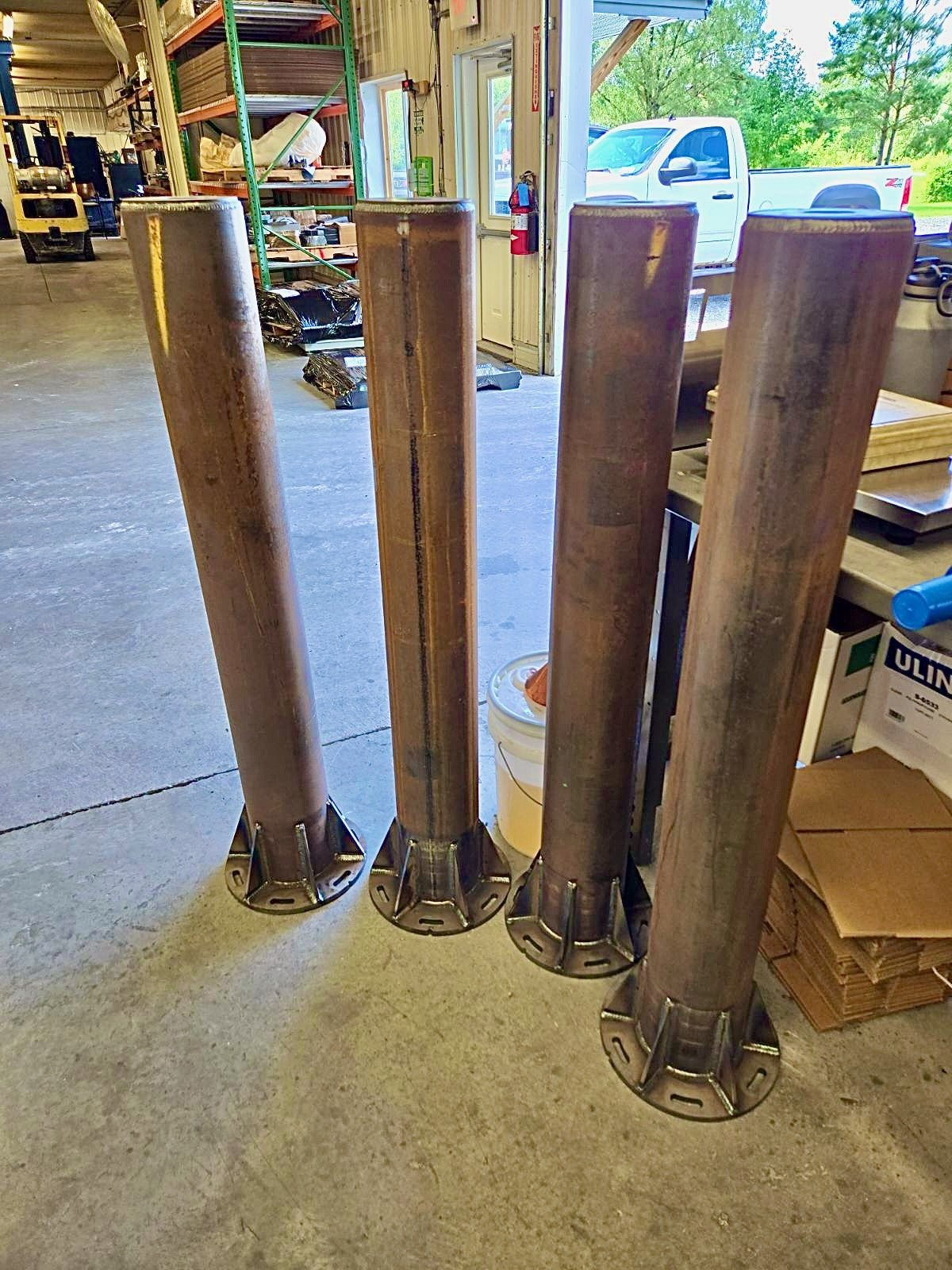
The final product - ready to go the painters!
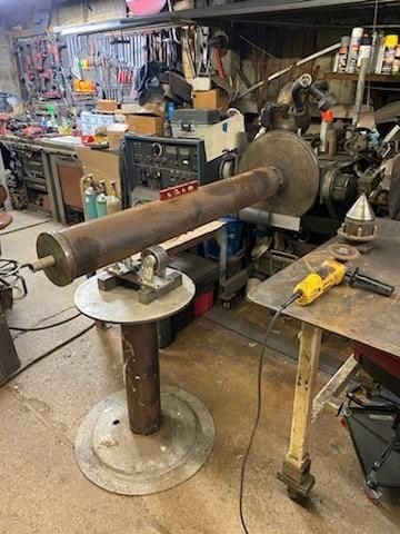
Set up on what looks like a lathe to hold and position parts for welding.

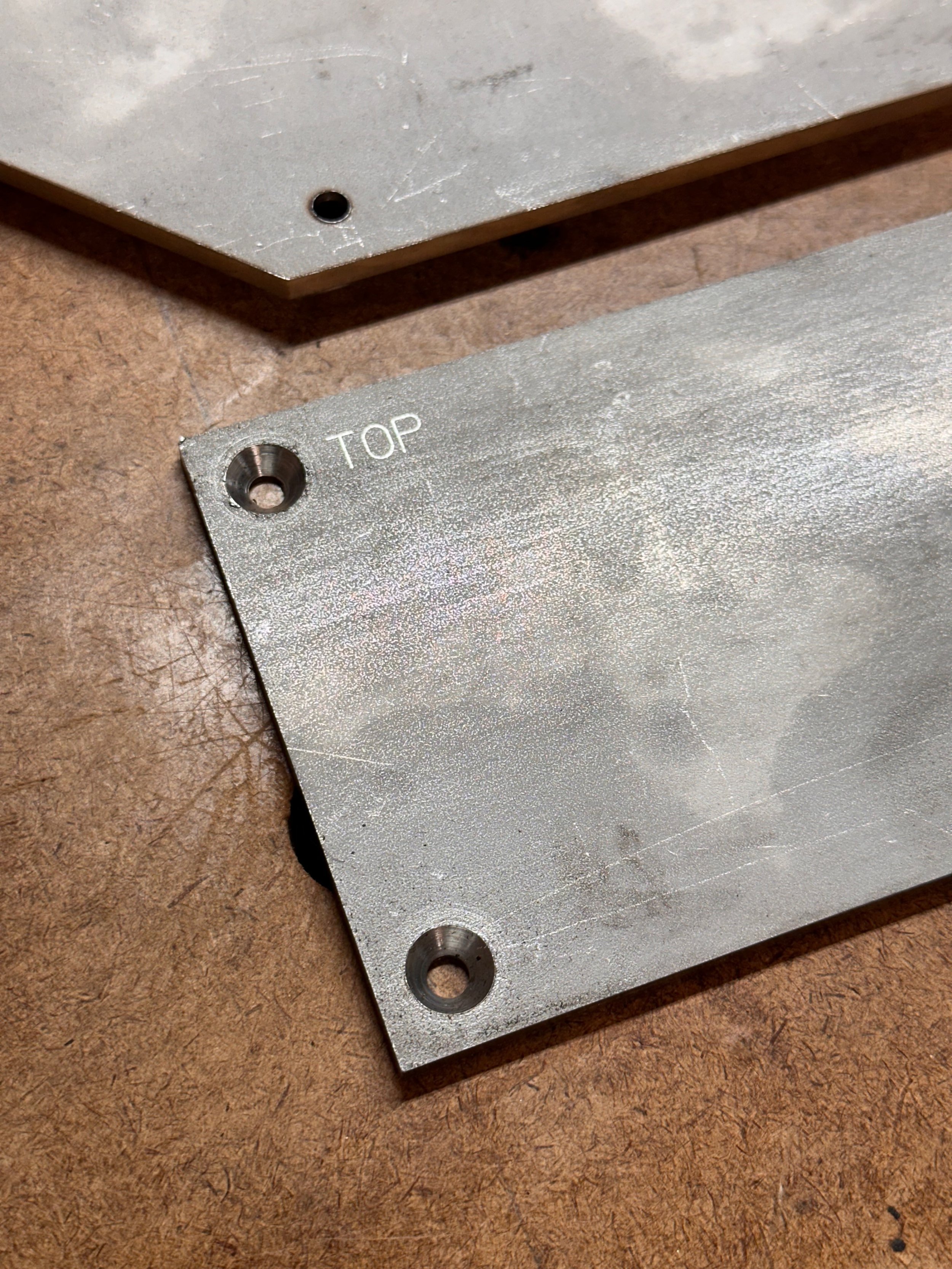
Most of the welding is now done!

A close up of the welds…

The Bottom of the Piers…

And the top!
Other Hardware
This week, Gary completed a few other parts that he was doing for me, and I was also able to pick up other pieces of needed hardware.
Flat Track
The day we cut the parts for the piers, we went over what else was needed. One of those items was the flat track.
Originally, we decided that we needed 40 feet of 3-inch-wide stainless steel. However, upon looking at samples of the flat wheels, we decided to go with 3.5-inch-wide steel. In addition, we decided to break the 40-foot length into reasonable sections and put a 45-degree angle where they met so there was a smooth transition from one piece to the next. Finally, we countersunk the holes. Here are the final pieces!

All of the sections of the flat track.
One of the square ends with counter sunk holes.

This shows how the sections will mate.
V-Groove Wheel Reinforcement Pads
In a previous posting, I discussed the selection of the V-Groove Wheels and was a little concerned that they would not be wider. Rick Abrecht suggested that we make some 3x5-inch steel plates with the same hole pattern as the wheels. When the wheels are bolted to the roof header, the bolts will go through the plates, strengthening the wheels for any lateral loads.
These, like all of the work that Gary produces, were perfect!
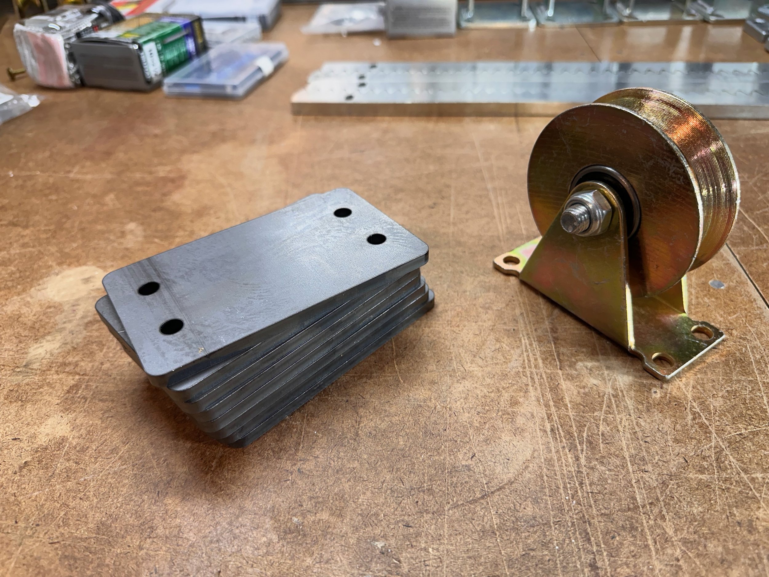
A sample V-Groove wheel and the stack of steel plates.

Here is the wheel on the plate.
L-Bolts and Nuts/Washers
I was also responsible for the L-Bolts that would be set into concrete for each of the piers. Each pier needs six bolts for a total of 24. These are 1/2 diameter x 12 inches long and are made of hot-dipped galvanized steel. In addition to the bolts, I needed galvanized washers and nuts. These we all ordered and arrived recently.
Once I get the Pier parts back from the painters, I will bolt these to the foundation plate and they will be ready for setting into the concrete forms!

L-Bolts plus washers and nuts.
Site Prep
A while back, I staked out the observatory's location, which I roughly aligned with North-South.
I wanted to make sure I had the alignment as good as I could, so I went out at night, used a laser lever and a compass app on my phone, and adjusted things as best I could. Then, I adjusted the corner posts to reflect walls that were 16 x 20 in size.
After thinking about it for a few days, I realized I had not ensured each corner was a true 90 degrees.
So, to test this, I measured the diagonals of the main building, and to my surprise, one diagonal was a different length than the other—by feet!
Yow! I had laid out a parallelogram, not a rectangle!
So I went back out and used the 3-4-5 method (google it!) to ensure 90-degree corners and fixed that problem.
When I talked to my developer recently about start dates, he asked if I could measure out a pad 3 feet larger than the building on each side. This pad will be prepared during excavation.
I had no sooner laid out the 3-foot pad when my developer told me that he and the excavator would be coming this morning to look at the work that needed to be done.
They will remove the topsoil, level the pad area, and then lay a foundation of gravel.
Trenches will be cut from the house to the observatory, and a trench will be connected to our existing shed. This will bring power and ethernet cables from the house and run power to the shed. (This last part has nothing to do with the observatory but makes sense to do at the same time).
This will be done in the next few weeks and sit there until the construction crew is available to start the build.

It's hard to see the staking in this image, show I (crudely) drew in some lines to show things. The yellow rectangle is the overall "pad" and the red is the observatory. The front-most red square is the observatory building and the rear-most red box is the outrigger section. The red mid-line is the North-South line.
Wrapping Up for Now
That’s where things stand today.
I will post a short item when the piers come back from the painters and when the excavation is done. So stay tuned…