
Observatory Project: Opening The Roof!
Date: July 23, 2024

Table of Contents Show (Click on lines to navigate)
NOTICE!
This post shares my preliminary design thoughts for a Roll-Off-Roof Observatory.
I make NO representations regarding the fitness or soundness of the designs and design decisions discussed.
Use this information at YOUR OWN RISK!
If you decide to build your own version of this project, you ASSUME ALL LIABILITY for your efforts and their results.
The Video Companion to this Post
Earlier Posts in this Series
I have been thinking about building an observatory for a while now - below are previous posts leading up to where I am today.
Observatory Project: Final Roof Track System Hardware Selection July 2024
Observatory Project: Designing Custom Steel Piers - Part I June 2024
Observatory Project: Galvanic Corrosion and a Change in Track Selection! June 2024
Observatory Update: Designing the Roll-Off-Roof Track System! May 2024
The Move is Complete, Now Pivoting to the Observatory Project! April 2024
An Observatory Project Update: Success! We Just Bought A Property and Will Be Moving! Nov 2023
An Observatory Project Update - One Year In Feb 2023
Goals for my Observatory Project March 2022
To Move the Roof, We Need…
… A few key things that we have not yet talked about much.
A motor to drive the roof
A linear gear and a drive gear that couple to the motor
A control system to manage the opening and closing process
Originally, I was looking at a gate drive motor on Amazon. I thought that this could be adapted to the roof application. some even had add-on modules allowing control signals to be sent via WiFi!
But as I dug into it further, I realized that none of this would easily integrate with various astrophotography applications without a lot of work - work that I did not really want to take on.
I wanted a control system that supported ASCOM drivers and would integrate with weather systems and all-sky cameras.
I remembered that the West Texas Group has used a SkyRoof Control System by InteractiveAstronomy to do this with their BYO Drive motor. So, I looked at Interactive Astrononmy’s (IAA) website and saw a control system that I thought I might be able to use with the Amazon Gate Motor.

The InteractiveAstronomy Webpage: https://interactiveastronomy.com/
So, I sent an email to IAA to see if this control system would be compatible with the motor I was considering buying.
I got a call back from Jim Collins from IAA and learned that the only other motors supported were the BYO motors and some specialty motors.
Jim had run into issues with the motor I was looking at buying, where stray electrical noise from storms could open the roof! Obviously, a system that erroneously opens the roof when a storm is coming through is less than ideal!
As a result, Jim sells basically the same motors where the electronics have been replaced with something more reliable for our application.
Since I was looking at having four piers and telescopes, Jim also highly recommended designing the observatory so that the roof could close, regardless of the orientation of the scopes.
Otherwise, the system has to have additional safeguards to ensure the roof is not smashing all of the telescopes while closing! This adds complexity and cost. This is accomplished by having a special photo sensor for each telescope that will ensure that each scope is a in a safe position. When this is true, then the roof can close.
First there is the cost of the extra sensor for each scope - this costs about $250 each! Then there is the issue of a scope that is not behaving well. Lets say the scope is in the way and will not respond to commands. This would prevent the roof from closing and put all of the scopes at risk.
So, ensuring the roof can close regardless of scope position is a very good strategy.
However, to do this, I had to raise the height of my walls from 6.5 feet to 7 feet. This does impact sight angles and how low I can aim the scopes. But I thought it was a needed trade-off. I think everything will be clear in this configuration - but things could work out such that I am off by a bit. I decided that if this were the case, I would add some counterweights to the end of the scope, and slide it down in its saddle a bit. I think they all will clear, however.
So, this is the approach I decided to take.
What the System Includes
The system I was interested in includes the following:
The motor
about 13.8’ of linear gear
A custom drive gear that moved the roof more slowly and quietly
A control system and master open/close switch
A custom wiring harness designed for my specific observatory
Magnetic sensors for sensing roof position
Software to control things via a computer.
I planned to order this and have the system in hand BEFORE the observatory build started. I wanted to have the contractor install this system with my supervision to ensure it went in the right direction.

The SkyRoof Motor and controller

The Basic SkyRoof control system.
Placing the Order
Once I had chosen my Roof Track hardware, I was ready to move ahead and place an order for the SkyRoof System.
Since Jim custom wires each system for each observatory, you need to contact Jim directly to place an order. So I called him. After going through the details, Jim said he would send me a PayPal invoice, and I would send him a copy of my observatory design so he could get started.
I paid the invoice, and that started the wheels rolling.
The system comes with 13.8 feet of linear drive gear, but I would need 20 feet for my roof. Jim had an Amazon link for ordering additional lengths and I placed an order for this as well.
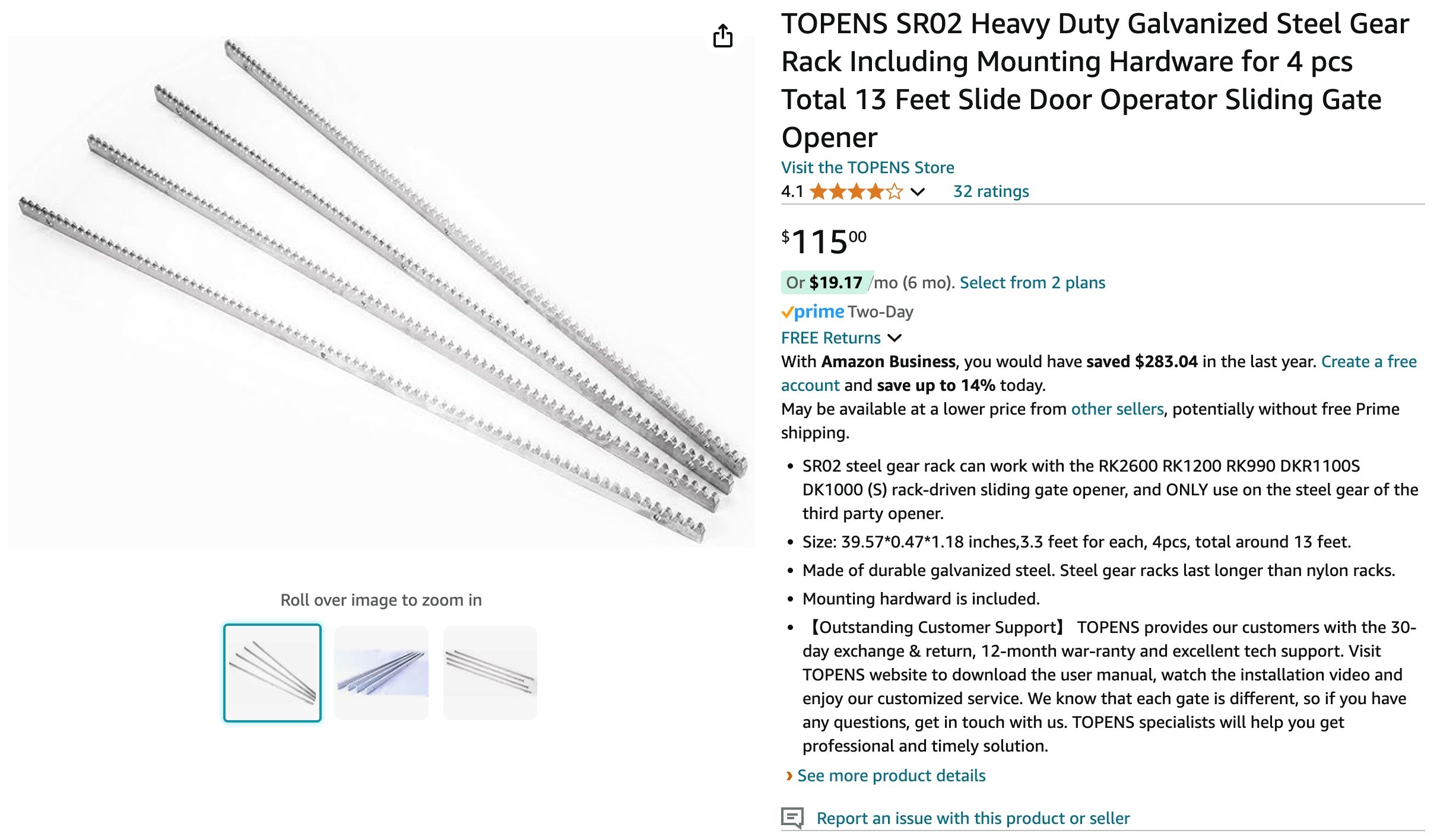
The Amazon listing for additonal linear gerar track can be seen HERE.
Picturing the Installation
Shortly thereafter, Jim provided me with images showing my observatory and how the system might be installed for my application.
The suggested approach hung the drive gear from a beam mounted on my roof scissor trusses, and the motor was positioned even with top of the north wall. We also briefly discssed another option of mounting it to the side of the roof.

Jim’s initial suggestion for mounting the motor and drive gears

Another view, showing that the Clockwise rotation of the motor opens the roof.
I talked this over with Rick Albrecht and he thought that the side mount option might be simpler and suggested this as a mounting method:

Rick’s concept for mounting the motor and drive gear.
I shared this concept with Jim, and he indicated that this would work fine and created another set of 3D diagrams to illustrate it.
In fact, Jim gave me a version of the 3D file, and I used the free version of Fusion360 to create other views. Thanks Jim! After playing with this design for weeks, it was great fun to explore it in 3D!

Jim’s updated view showing the new mounting method.

This view shows the motor and gear from a different angle. Clockwise still opens the roof!

A side view.
Here is a nice view that shows inside of the observatory.

View showing the piers and the basic features of the observatory.

The proposed location of the control unit and the magnetic sensors.

Basic Wiring Layout.
This looked like it would work great!
I need an outlet near the Drive motor to power it. Eventually, I will use a UPS to provide backup power to the drive, so this would likely be mounted on a shelf below the motor.
I will also need an outlet near the control unit. Again, a UPS would be needed to power this unit and the observatory control computer.
A Minor Tweak
One issue is that with the side-mounted beam, I realized there would be no way to use the manual roof-lockdown latches I was planning on. The best way to handle that, in my mind, was with gaps in the beams at strategic locations. The gear needed to be continuous, but the support might be interrupted to leave room for the lockdowns.
After reviewing several ideas, the best one seems to involve moving the beam up on the roof header a bit - leaving roof for the latches.

Rick’s concept diagram for this change.
We could even use a 2x4 for one of the beam supports, but we would have to make sure that the latch hooks will not interfere with other things area - like the motor iteself - as you can see here:

Another of Rick’s views showing the need to ensure clearance for the Clamp hooks.
What’s Next?
Now that the order is placed, the delivery time will be a few weeks.
In the meantime, I will mock up the mounting method and ensure that there is enough clearance for my Manual Lockdown Latches.
In addition to this, I have tree work being done very soon to better prepare the site, and I have parts at the welder for my four custom Piers.
The next area of attention will be on wiring the observatory.
Stay Tuned!