Observatory Update: Building the Structure!
Date: Nov 29, 2024
Table of Contents Show (Click on lines to navigate)
NOTICE!
This post shares details for the construction of my Roll-Off-Roof Observatory.
I make NO representations regarding the fitness or soundness of the designs and design decisions discussed or the suitability of the construction details shared.
Use this information at YOUR OWN RISK!
If you decide to build your own version of this project, YOU ASSUME ALL LIABILITY for your efforts and their results.
Earlier Posts in this Series
I have been thinking about building an observatory for a while now. Below are previous posts that have led up to where I am today.
Observatory Update: Laying the Foundation Nov 2024
Observatory Update: Custom Telescope Piers Part 3 - Painted and Complete! Sept 2024
Observatory Project: Breaking Ground! Excavation Complete! Sept 2024
Observatory Project: A Final Update Before We Break Ground! Aug 2024
Observatory Project: Opening The Roof! Aug 2024
Observatory Project: Final Roof Track System Hardware Selection July 2024
Observatory Project: Designing Custom Steel Piers - Part I June 2024
Observatory Project: Galvanic Corrosion and a Change in Track Selection! June 2024
Observatory Update: Designing the Roll-Off-Roof Track System! May 2024
The Move is Complete, Now Pivoting to the Observatory Project! April 2024
An Observatory Project Update: Success! We Just Bought A Property and Will Be Moving! Nov 2023
An Observatory Project Update - One Year In Feb 2023
Goals for my Observatory Project March 2022
Construction Starts!
Once the holes were drilled and the concrete was poured, we were ready to start construction.
I have already published two videos showing a kind of sped-up flow of the construction work. I will include those below. However, the goal of this post is to provide some further information on the various steps shown in the videos
The Videos
Putting the Poles in the Holes
To lower costs, I would be using a Pole-Barn method of construction.
In this case, the poles or columns used are Perma-Columns. These are engineered pieces where the lower 5’ consisted of 10,000 PSI concrete with internal 60,000psi rebar mated to an upper wooden beam fabricated from three 2x6 timbers that are glued and then machined to create a flat square format. The junction between the two is accomplished with 1/4-inch powder-coated steel brackets.
The concrete goes into the ground and will never rot. While the woo portions are above ground and protected from the elements by the rest of the building.
These are quite heavy, and we had 10 of them put in holes around the perimeter of the building.
The stack of 10 Perma Columns used in this project.
The Perma-Column Design.
This was done with the use of a strap and a Bobcat with lift arms. This was handled by Dana and Rodger, who made it look easy!
Placing a column.
Once positioned, the columns were dropped into the holes. They had to be carefully positioned, straightened, and secured with bracing. Note the string lines used to mark the positions needed.
Placing and Bracing. Note Rodger is using a 2×4 to leverage the column where it needed to go.
Once all of the columns were placed and braced, the rest of the framing could begin. The holes were then backfilled.
Girts and Skirtboards
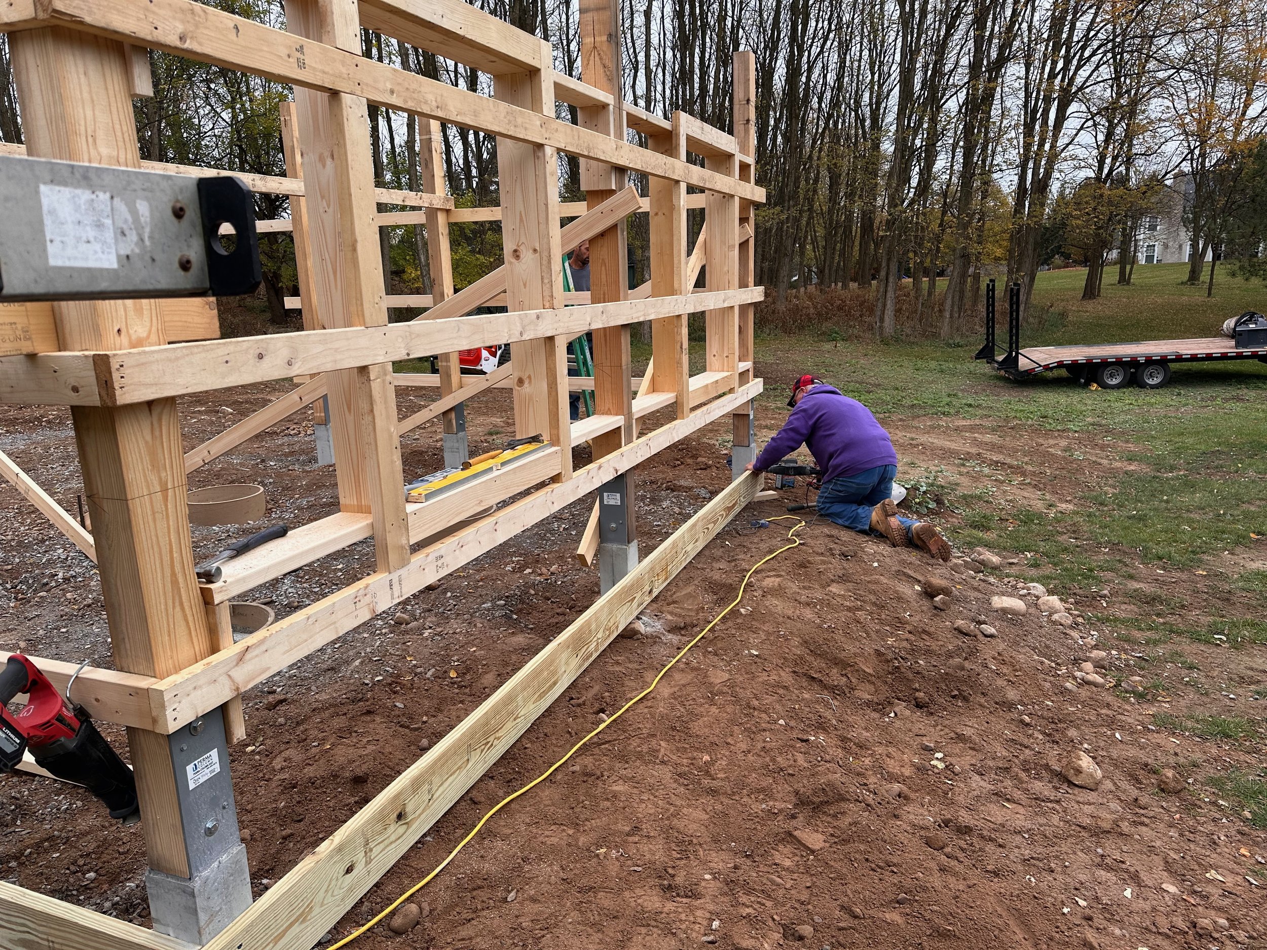
Now that the columns were in place and braced, the girts and skirtboards could be added. The girts were regular 2x4’s nailed horizontally. These add strength to the structure, and provide a nailng surface for the plywood when the cladding is added to the building.
Adding the Gerts
The Skirtboards were in contact with the ground, so they needed to be pressure-treated.
Once these were in place, the rough framing for the two windows on the South face were done, along with the framing for the door.
Skirtboard installation.
Prepping the Steel
Before proceeding further, we needed to prepare the steel for the roof's supporting outrigger and the building's wall headers.
The blueprints called for 4x4 steel box channel beams that were 1/8-inch thick. What was delivered was 1/4-inch thick! This made the steel stronger, heavier, and more challenging to deal with than expected.
The first step was to cut the vertical uprights to size.
These were bolted to the foundation pads, and a laser was used to mark the appropriate height. Dave then cut them with a chop saw. Once cut, they were remounted to the foundation pads.
Finally, the Columns were all marked and cut to the same height.
This provides the mounting points for installing those massive 40-foot-long steel beams.
This allowed the correct heights to be measured with a laser level.
Cutting the posts.
Remounting the cut posts
Cutting the columns.
Next, the 45-degree cross-braces used in the outrigger were cut.
This was a three-step process.
First, they were cut to length with a chop saw.
Then the 45-degree angles were cut with a torch. I was surprised at how quickly Dave could cut this thick steel.
Finally, the cuts were then smoothed off with a grinder.
Cutting the cross-braces to length.
Closer up.
Cutting the 45-degree angles.
A fresh cut - this would then be ground smooth.
Mounting the Steel
I thought mounting the 40-foot-long beams would be a nightmare. They are very long and very heavy.
But I was mistaken.
A Bobcat with lifting arms, a heavy-duty strap, and some good technique made it look easy to put the first one in place. Dana was driving the Bobcat, and Rodger was guiding the beam. It was positioned on the top of the Perma columns and blocked into place with wood blocks screws. Then Dave quickly tack-welded to the steel uprights.
The west one was done first, followed by the eastern beam.
Lifting and moving the first beam.
Positioning the second beam.
Dropping it into place.
Welding the eastern beam to the steel uprights
Tack Welding the beam onto the steel uprights.
Once these were down, the three crossbeams were cut to length, hoisted into position, and then tack-welded in place.
Positioning the first crossbeam at the back of the observatory.
Another crossbeam.
Welding the last crossbeam into place.
Dave then made a series of custom brackets with screw holes that were welded to the beams near the columns so that the beam could be securely bolted to the columns.
Finally, all of the tack welds were then replaced by a complete welds of the seams.
Bracket conecting steel to column.
Bolting the columns to the beams.
The final task was to mount the two-foot-long 45-degree cross braces. These were clamped into position and then welded.
These cross braces might be overkill. They would have been needed if the steel was only 1/8-inch thick. But with 1/4-inch thick steel, the outrigger without these braces was mightly solid! I guess having them makes it even more solid!
Clamping the cross braces into place.
Once clamped, the cross braces are welded.
Building the Roof Headers, the Wheels, and the Track
The roof headers were going to be heavy. I wondered how Dana and Rodger would deal with it.
The headers are the roof's foundation.
These wood beams are constructed of three 2x6s with 1/2-inch plywood spacers sandwiched between additional 2x6s on the top and bottom. Keep in mind that these babies are 20 feet long! So they would end up being very heavy.
This is where Dana and Rodger surprised me.
The tops of the steel beams came out very flat and level, so they decided to build the headers on the top surface of the long beams!
It makes sense really. Each board was not heavy and could be easily lifted to the beam and nailed in place there - one at a time.
So, they built the east header first, which was made precisely according to the blueprints' specs.
The east header.
Finishing up.
Then, they built the West header. This one needed some additional spacing. The V-Groove Wheel stack on the West measures about 1.5 inches shorter than the flat wheel used on the East side.
So, when building the header, the team just added two layers of 3/4 plywood to the mix to balance this off.
Starting on the west header.
Finishing up.
With the headers built and resting on the beam, mounting the wheels on one side was relatively easy.
A centering line was marked using a snap line, and the wheels were positioned and bolted on!
Mounting the V—Groove wheels
Finishing up the V-Wheels.
The next step was to move the header out of the way so that we could weld the track onto the beam.
First, Rodger built some support arms on the top of the wall, and then the header was carefully laid on its side on these arms so they were out of the way.
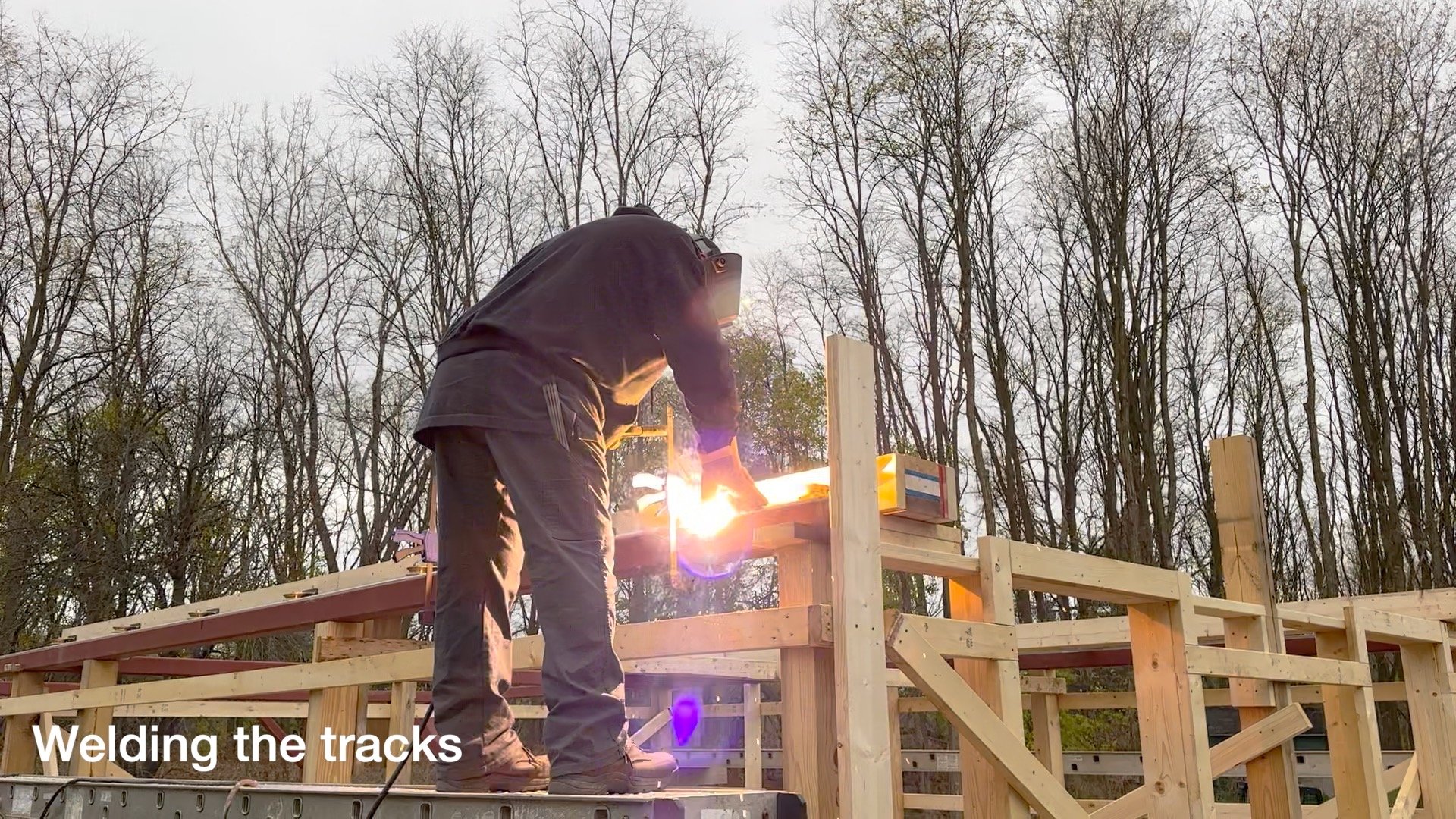
Then the track was positioned and clamped on the top of the steel beam, and Dave welded them in place.
Welding the initial section of V-track.
Welding the initial section of flat track.
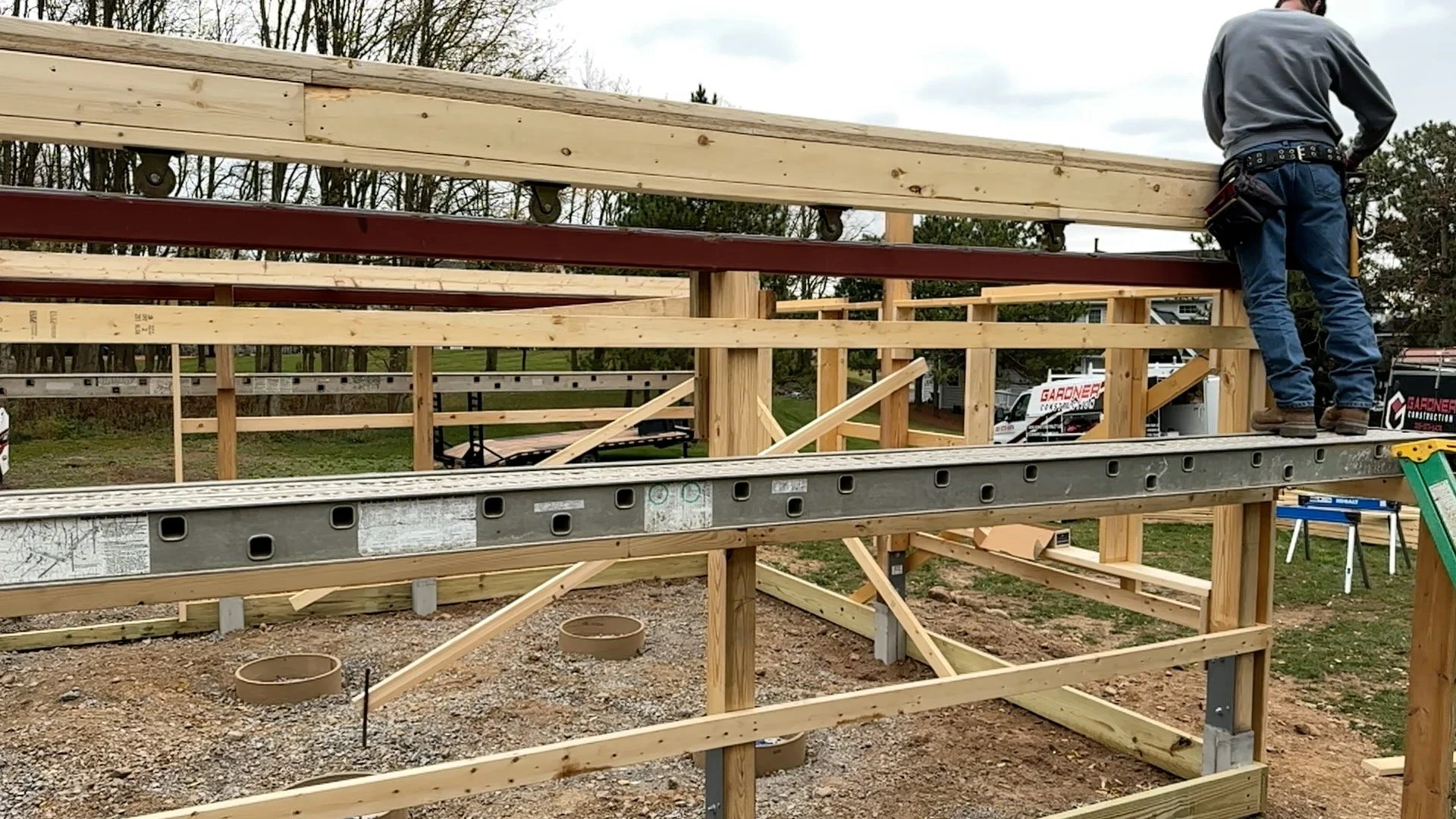
Once this was done, the header was leveraged back up and into place with the wheels sitting on the track!
Then a 2x6 board was mounted to the North and South face of the building - lined up with the ends of the header. This was then bolted to the header, holding everything in place!
The wheels are now on the track!
The end of the header showing the board holding everything up.
The flat wheels on the flat track.
Setting The Roof Trusses
The next day, after building the headers and setting them up on the wheels/tracks, it was time to install the scissor trusses for the roof.
The headers were held in place by wood rackets, but before things could proceed, they needed to ensure that the headers were secured in a position where they were absolutely square, parallel, and the correct distance apart.
Checking Squareness.
Checking distance apart.
Once this was done, it was time to start. The trusses were installed one by one with 2x6 blocking between each. As these went in, then they were temporary braced in position.
The first truss goes up!
All of the trusses in place!
The next day, progress continued
Purlins were nailed on the trusses.
These will hold the metal roof in place, and they also act as another form of bracing for the trusses. As these we installed, each truss was checked to ensure it was in the proper place before being nailed. Some trusses had a bit of a curve to them, and this process straightened things right out. Once the purlins were in lace, they were trimmed to length, and the roof edges were framed.
Adding Purlins on the east side.
Framing the roof on the northeast end.
Also - the proper cross bracing for the roof trusses was applied.
Once the first side was done, a similar process is used to complete the other side.
Adding the west side purlins.
Finising up.
Testing the Roof!
With the Roof completely framed, we wanted - and needed - to try opening it for the first time!
We were anxious to see how hard it was to move, and we needed to move the roof away from the closed position so that track stops could be welded at the south ends of the track.
First, we needed to complete the tracks on each side and go to the very end of the beams. Then, the stops were welded in at the back.
Welding in the last bits of track.
Welding in the stop plate.
At this point, we unbolted the headers and tried moving the roof for the first time!
Moving the roof for the first time! A little bit bumpy due to weld residue.
Dana, standing on the scaffold, was able to push it open.
It took a bit to get moving, but it was easy to keep going once in motion. It was a little bumpy at first, but this was due to some rough weld points.
The seams between the sections were welded on both the flat and the V-Track. This would make the track solid and stable over time, but the process leaves some residual metal that were the cause of the “bumps.”
To resolve this, Dana went in with a grinder and smoothed off the rough junctions. Roger followed with a sander and polished things even more!
Smoothing off the track.
Once this was done we tested it again and the motion was now super smooth and quiet as it rolled! Just what we hoped for!
Very smooth after grinding down welding seams.
The roof, all the way open!
Cladding the Walls
With the roof framed and tested, it was time to get move on with the cladding of the walls.
With Pole barn construction methods, the first step is to install 2x4 girts, which will provide the mounting support for the plywood walls. These are installed on all sides, and the plywood can be quickly mounted to the walls.
Plywood going into place.
The cladding was finished around the doors and windows and the plywood was cut to expose them
Cutting a window opening.
Installing plywood around the door.
The plywood cladding will act as a support for the future vinyl siding - but more importantly, it greatly enhances the strength of the building.
Cladding on the lower building complete.
Putting on The Roof
We are starting to push into November. So far, the weather has been kind to us, but we really want to get the building somewhat waterproof before poor weather descends upon us. The next step is installing the roof panels.
I opted for a metal roof for several reasons:
It was inexpensive compared to other materials
It was light; I wanted to keep the roof light so we could move it more easily
It was smooth - hopefully, snow would come off the roof easily!
I chose a Charcoal color.
Not black - that would cause the sun to heat it too much during the day.
Not white - as that would get dirty and show the pollen in the spring.
So this darker gray seemed to fit the bill.
The first step is to put the drip edge on.
Installing the drip edge.
Finishing up.
Then, the steel panels had to be punched.
This provides a nice clean hole for screwing in the roof. Drilling the holes can leave a jagged edge that can cause rust to form prematurely.
While most pole barns just install the metal panels onto the purlins, I opted to install a thermal blanket first. This blanket is a foam sheet with an aluminized face, and it helps with condensation and heat transfer issues.
Punching the holes.
Cutting the foam thermal blanket.
The panels are then mounted to the roof.
I was amazed to see that the panels could withstand the weight of a man walking on them, which was necessary for installation.
However, the crew did wear clean sneakers so they had better traction and would not slide off the roof!
Installing the first section of the thermal blanket.
And the first steel panel.
Finishing up the east side.
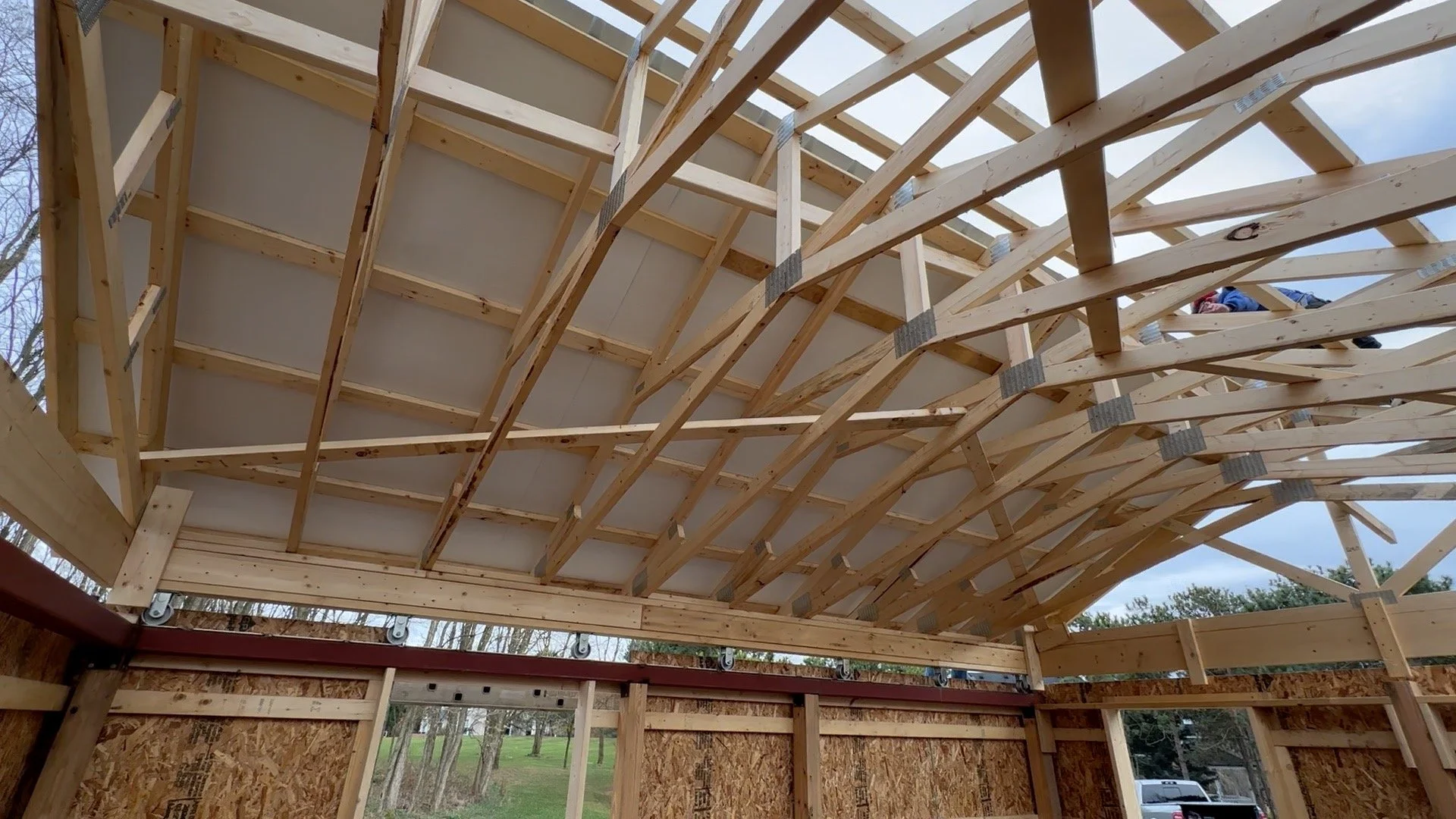
The east panels as seen from the inside.
Finishing up the west side.
The west panels as seen from the inside.
To complete the roof, the framing of the gables has to be completed and the plywood cladding added.
Finishing the gable framing.
Adding the cladding to the South side.
Adding the cladding on the north side.
The final piece!
The front and back roof trim edges are added.
Adding the frst roof edge trim piece.
Roof edging complete!
To complete the roof the ridge vent must be installed.
First, foam is applied to each side to prevent bugs and spindrift from entering the building, then the vent is screwed to the top of the ridge.
Applying the filter foam to the ridge vent.
Installing the first ridge vent section.
More foam application.
More ridge vent installation.
The roof is now complete and waterproof - a major milestone!
Wrapping the Building
While the roof keeps the rain out, the rest of the building has to be made weatherproof. This is done by wrapping the building and installing the windows.
Windows are not really needed for an observatory, but we wanted the observatory to look nice from the house, so we designed it to look like a little cottage—thus the windows. At some point, I will build decorative shutters to go with them!
The door is a custom size, so a cut-down door has been ordered and will take another week or so to get here.
The wrap is up on the south wall, now the windows are cut.
Installing the second window,
installing the first window.
Wrapping the gable.
Soffit and Trim
The last bit of work for this phase is to block in and add the soffits to the eaves, along with the final white trim.
Soffit installation.
Installing the aluminum white trim.
More soffit installation.
Finishing up.
Testing the Roof
Now that we had added everything to the roof the metal roofing, the soffits, and the trim - we wanted to see how the roof roll was with the additional weight.
Test opening with the final roof weight.
Fully open and a view of the skies and trees from inside.
It was heavier, but it was still relatively easy for one person on a scaffold to get it moving and once moving, it was easy to keep moving. The roof's weight is around 4,000 lbs, and the motor is rated for 7,000 lbs, so we should be good!
That Completes this Phase!
And with all of that - the observatory is basically weatherproof, and the roof now opens!
The weather resistant observatory!
The next phase will involve getting the rough electrical in and pouring the slab. So stay tuned!


