
Whispering Skies Observatory: Final Overview, Layout, and Capabilities
February 5, 2026
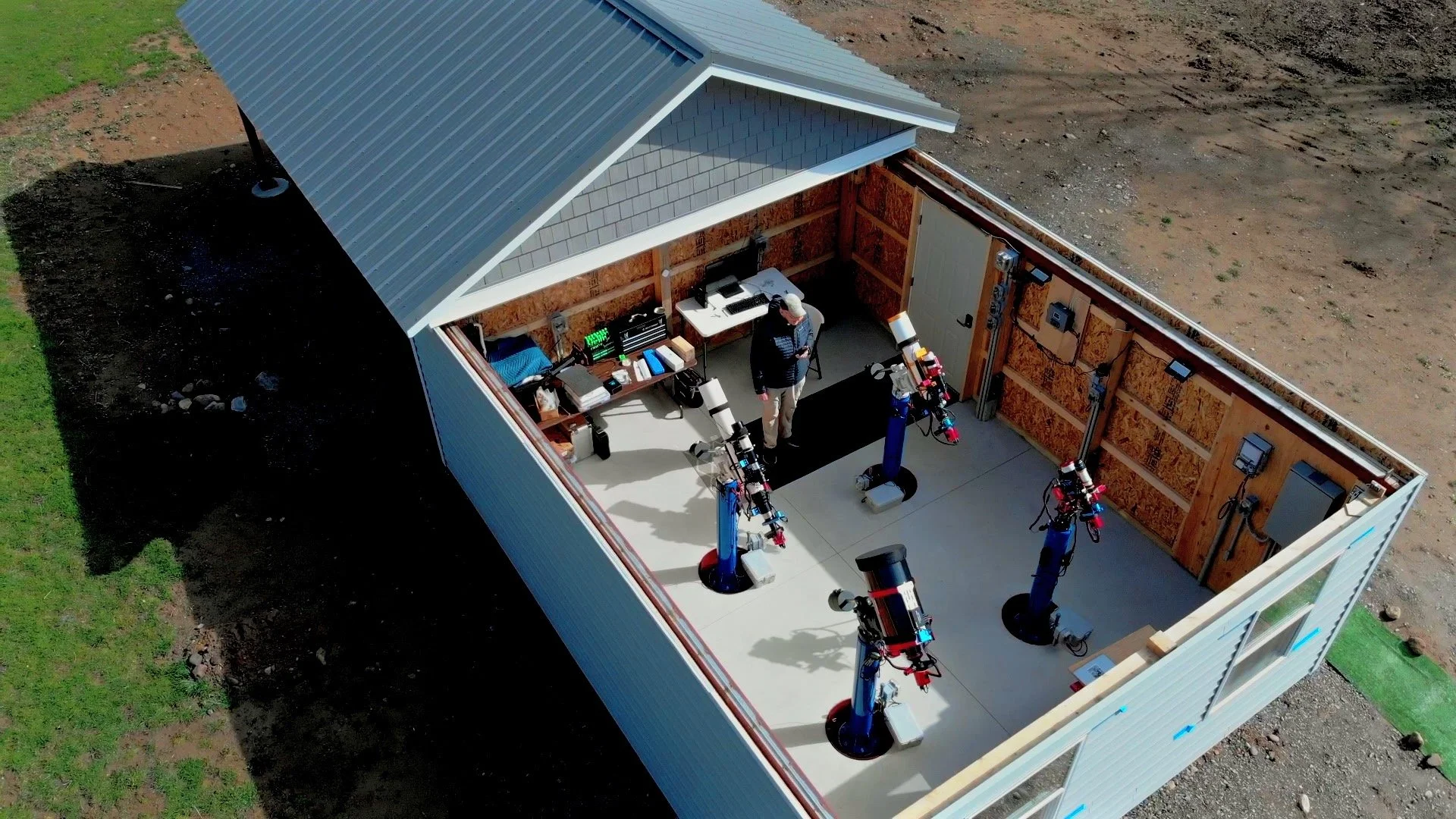
An overhead drone view of the Whispering Skies Observatory with the roof open.
Table of Contents Show (Click on lines to navigate)
Introduction
I’ve documented the design and construction of my roll-off-roof observatory across a long series of posts—starting with early ideas and goals and progressing through execution and commissioning. That series tells the story of how this place came together.
This post is different.
This is the “as-built” overview: what the observatory is today, how it’s laid out, how it’s powered and networked, how the roof and weather safety are handled, what each pier platform is for, and how I run a typical imaging night. If you’re new to the project, this is the best place to start. (If you want the full build history, I’ll link back to the complete series at the end.)
The 60-Second Overview
Whispering Skies Observatory is a 16’ × 20’ roll-off-roof observatory located south of Rochester, New York.
The structure is based on a pole-barn concept using engineered Perma-Columns, with a poured slab floor, and four custom steel telescope piers—each in its own foundation, isolated from the building. This observatory was designed for reliable, repeatable astrophotography with minimal operational friction.
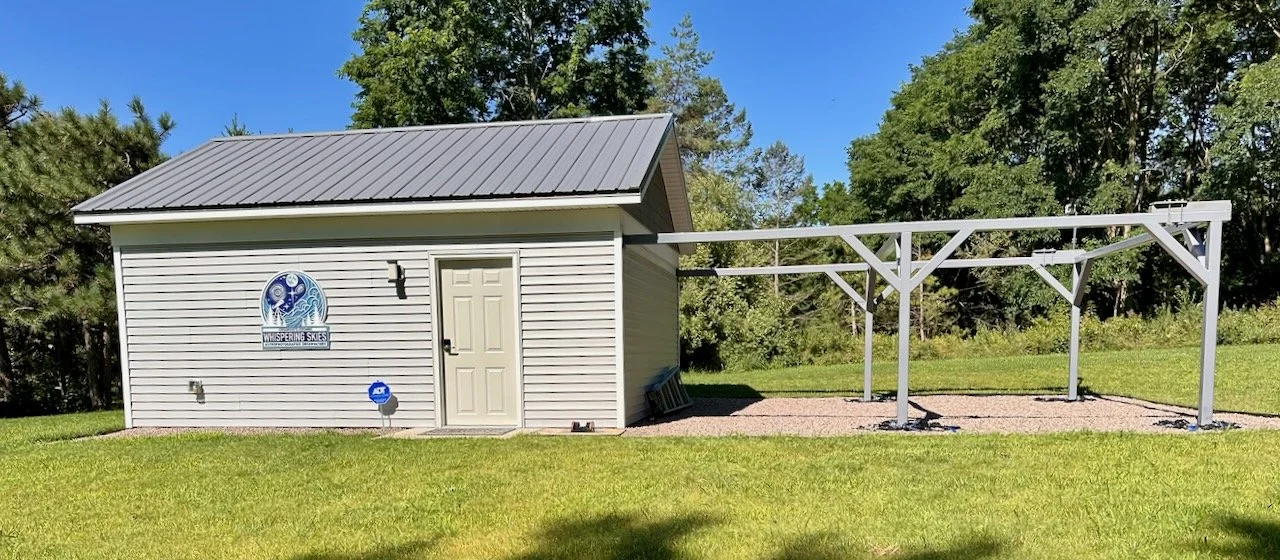
Whispering Skies Observatory as it is today with lawn restoration, final paint and finish, and the observatory sign in place.
It started as a 16’ × 16’ concept, but I expanded it to 16’ × 20’ for a specific reason: to support placing cabinets and countertops on the north wall to make the interior a functional workspace—not just a pier shelter. The interior is organized around two practical zones:
Tools / OTA Configuration workspace on one side (for upkeep, cable work, updates, repairs, and general project work)
Computer / Operations workspace on the other side (for running sequences, monitoring, and managing the imaging workflow)
The roof is powered by a SkyRoof motor and control system from Interactive Astronomy, and I’ve installed a SkyAlert weather system that integrates with it. Power is serious: 100-amp service was brought in from the house (about 180 feet), along with multiple Ethernet runs that serve as a hardwired backhaul for a mesh router node mounted in the observatory.
Five design decisions matter enough that they belong in this summary up front:
Footprint expansion: 16×16 → 16×20 to make room for real cabinetry, countertops, and usable work zones.
Steel Supports: Using 4x4 steel beams in the wall header and outigger eliminates concerns about shrinking and warping. Pressure-treated lumber
Roof weight: The moving roof uses a metal roof specifically to reduce moving mass and improve long-term mechanical reliability.
Roof security: The roof has lockdowns that secure it in the closed position during wind and severe weather events.
Drainage: I chose not to use gutters and instead installed French drains around the building to manage water and reduce seasonal maintenance issues.
The result is a facility designed for one thing: reliable, repeatable astrophotography with minimal friction—and the ability to operate it comfortably and safely.
Whispering Skies Observatory — Key Specs (As Built)
A quick snapshot of the facility design choices that matter in day-to-day operation.
- TypeRoll-off-roof astrophotographic observatory
- Footprint16’ × 20’ (expanded from 16’ × 16’ to support cabinets/countertops and two work zones)
- Work zonesTools / maintenance side + computer / operations side
- PiersFour isolated steel piers on separate foundations
- Roof typeMotorized roll-off roof
- Roof coveringMetal roof to reduce moving mass and mechanical load
- Roof motorIA SkyRoof motor and control system
- Weather monitoringIA SkyAlert system
- Wind securityManual lockdowns for maximum security
- GuttersNone (allows snow to slide off)
- DrainageFrench drains around the building perimeter
- Power100-amp electrical service and distribution sized for imaging gear + roof system
- LightingWhite (work/setup) + red (night operations)
- Wi-FiMesh Wi-Fi router in the observatory
- BackhaulEthernet hardline backhaul supports the mesh network
Optional Deep Dives
If you want more detail beyond this overview, these pages go deeper (build history, platform details, and a guided tour).
🏗️Full Build Series
From early goals through construction and commissioning.
🧰Platform Overview
All four rigs side-by-side and how I choose a platform for a target.
🎥Video Tour
A guided walkthrough of the observatory and workflow.
🧾2025 Snapshot Post
Earlier “facts” list and milestone summary.
🔭All Telescope Gear Pages
Browse the gear pages by telescope/platform.
🗣️Talks & Presentations
Observatory tours and other outreach material.
1) Why This Observatory Exists
This observatory was built to reduce overhead and increase throughput.
After six years of setting multiple scopes up in a driveway with only a 3-hour window on the sky through a gap in the trees, I was ready to step up my game.
The old days of setting up in the driveway. (click to enlarge)

The limited section of sky that I had at my old location (click to enlarge)
The goal was not just convenience; it was throughput.
If I can take the “overhead tax” out of every imaging session—polar alignment, cable management, hardware setup, recovery from weather—then I can spend my time collecting photons instead of wrestling logistics. It is a practical path to collecting higher-quality data throughout a season—especially in a climate where clear nights are sporadic, and conditions can change quickly.
A second design goal was durability. I didn’t want a structure that would slowly drift, rack, or warp in ways that show up months later as mechanical issues.
2) Site Realities and Water Management
Buildings fail in boring ways long before they fail in dramatic ways. Water is one of those boring failure modes that quietly creates ongoing problems—erosion, splash-back, ice issues, persistent dampness at the perimeter, and the kind of seasonal maintenance that becomes a reliability tax.
That’s why I took a direct approach to drainage:
No Gutters. Engineering gutters on a rolling roof is tricky, and they can be problematic in winter. They freeze up and can act as a barrier to snow sliding off the roof. The roof was designed to handle static snow loads, but it cannot support that weight when rolling. Without gutters, the smooth metal roof allows snow to slide off easily.
French Drains around the building to handle runoff and move water away from the slab and perimeter. Gutters handle run off, and without them, rain will drain on the edges of the building and potentially undermine the slab floor. In addition, the observatory is located on a hill. Melting snowpack can run down the hill to the observatory. To handle both situations, French drains were installed around the observatory footprint, with two separate drains that discharge to lower elevations. This should ensure the integrity of the building and outrigger foundations.
Another fortunate factor is that the ground on which the observatory is built has about 2-3 feet of sandy loam with a layer of cobbles beneath it. This is a result of glacial activity in the area. This provides excellent drainage in the area as it is.
This image shows where the French drains were to go, along with the drain outflows. (click to enlarge)
Installing the French drain at the back of the outriggers. (click to enlarge)
This strategy prioritizes long-term stability and reduced maintenance—both of which matter when the goal is reliable operation.
3) Structure and the Roof System
The Building Structure
The first thing done was excavation. The hillside was reshaped, and a level construction pad was established that was 3 feet larger in each dimension of the building. Then 10 inches of crush-and-run gravel was steam-rolled into place.
The observatory is built around a durable pole-bar approach using engineered Perma Columns. These columns feature a steel-reinforced concrete base and a milled, laminated beam upper section. These are very strong and long-lasting.
Each pole has its own foundation, a poured slab floor, and four isolated pier foundations. The key design principle is separation: the telescope foundations are isolated from the building so normal foot traffic and day-to-day use don’t transmit vibration into the imaging platforms.
The engineer PermaColums showing the concrete base and the laminated uppers. Behind them, you can see the 4×4 box columns used for construction. (click to enalrge)
Details on teh PermaColumns (click to enlarge)

Here his the basic design I went with.
Another key aspect was the use of 4x4 steel box beams with 1/4-inch thick walls for the wall headers and outriggers.
This was done to ensure rigidity and to avoid the shrinkage and warping that pressure-treated lumber can experience. Such issues can cause significant problems with the rolling roof tracking system over time.
One design detail I’ll call out because it surprises people: the two south wall windows are primarily aesthetic—I wanted the building to read like a cottage from the house rather than an industrial box. They’re managed with blackout curtains, and in summer, I can drop fans in the windows to help cool the space before imaging.
After construction and the French drains were installed, the entire construction pad was delineated with plastic edging, and the area was finished with weedcloth and 4 inches of crushed granite. This dressed up the perimeter of the observatory, including the space under the outriggers, in a way that looked nice and facilitates better drainage.
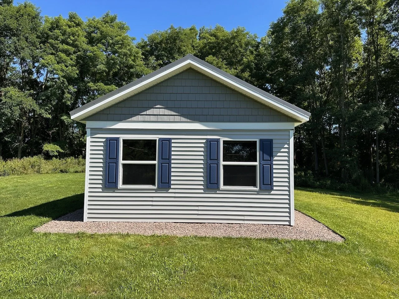
The southern face of the observatory showing the two windows. This makes the observatory look more like a cottage from the main house.
The Roll-Off Roof: Motion, Stiffness, and Weight
A roll-off roof is a moving mechanical system. Over time, the systems that work well are those built for stiffness, alignment, and predictable motion.
Three choices were central here:
A Seven-Foot Wall Height - this allows the roof to close regardless of the telescopes' position. This way, the roof can be quickly closed if the weather changes without requiring the four scopes in the observatory to move to the home position first. This important decision greatly simplified the control system, and now there is no need to sense that all scopes are out of the way before closing the roof. In an emergency, you don’t want to mess with that. You just want the roof to close.
The Use of Steel 4x4 structural members to form the wall headers and outriggers. This was done to ensure rigidity and to avoid the shrinkage and warping that pressure-treated lumber can experience. Such issues can cause significant problems with the rolling roof over time.
Track/Wheel System designed for robust tracking. The use of a V-wheel/track on the west wall and a flat roller and track on the east wall prevents binding from any minor alignment issues over time. The wheels are rated to easily handle the roof's weight for rolling and static snow loads as needed. In fact, I added more wheels on both sides than necessary to ensure good tracking.
Metal Roof. A metal roof has several advantages in this application. It reduces the weight of the moving roof and reduces the load on the wheels/track and drive system. The smooth finish lets snow slide off easily. And finally, it was lower in cost.

Testing the rolling roof for the first time. This image shows the steel framework supporting the tracks, and the wheels riding on those tracks.
Reducing moving mass matters. It lowers stress on components, reduces motor load, and generally improves long-term reliability and consistency.
The steel header and outriggers, and the “V” and “Flat” tracks, provide a firm foundation for roof movement. The Skyroof System by Interactive Astronomy provides the motor and control system that drives the roof. Weather integration is handled through SkyAlert (also provided by Interactive Astronomy), which integrates directly with the Skyroof system. This provides a way to close the roof when weather changes require it.

Interactive Astronomy’s SkyRoof System, showing the Motor, track, and control box
The SkyAlert weather monitoring system, along with some charts produced by the software (click to enlarge).
Roof Safety and Lockdown
A roof that is “closed” is not automatically “safe.” Wind events happen. Storms happen. The observatory includes heavy-duty manual roof lockdowns to secure the roof in the closed position. This is one of those unglamorous details that gives you confidence during storms with heavy winds!
The customized lock down clamp. There are four, one at each corner of the observatory. (click to enlarge)
4) Interior Layout: Operations, Storage, and Workspace
The footprint change from 16×16 to 16×20 was driven by interior function. A smaller building can protect equipment, but it often forces compromises that become persistent annoyances. I wanted to ensure I had space for storage and a workspace with countertops.
The southern area is about operations. It consists of four isolated foundations holding 4 heavy-duty custom-designed Steel Piers. These will hold four telescope platforms and have power routed to each pier.
The completed custom steel piers. (click to enlarge)
The base of each pier, showing the custom wedge-shaped “washers” (click to enlarge)
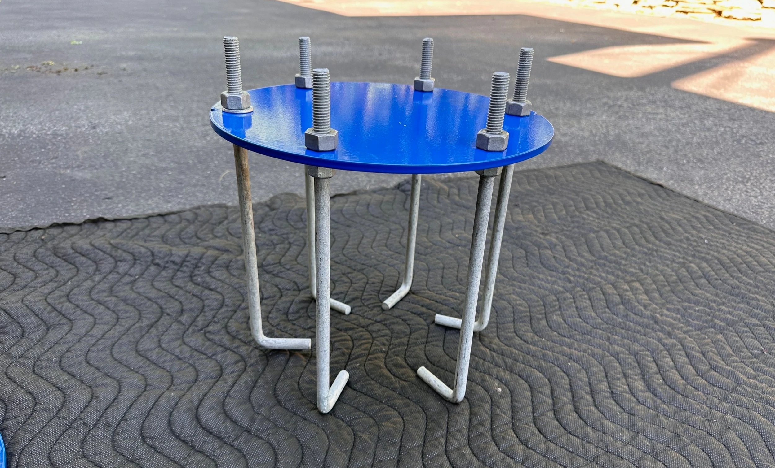
This is the bolt plate that was set into each pier foundation. (click to enlarge)

The four piers now mound onto their foundations.
A 16x4 section on the north side of the observatory is about storage, tools, a workspace, and a computer station.
The area is planned around two working zones:
Tools and Maintenance side
Countertops for allowing work on camera stacks and OTAs.
Cabinets for tool and parts storage
Suitable workspace lighting
Computer and Operations side
A dedicated computer station
Comfortable monitoring and control
A stable “command center” mindset
Storage for computer accessories, cables, etc.
This is a real productivity multiplier because it reduces friction across everything surrounding imaging: configuration changes, cable management, repairs, upgrades, and troubleshooting.
The North Wall Work and storage space, shown with the roof open. Tools and workspace to the left, computer area to the right. (click to enlarge)
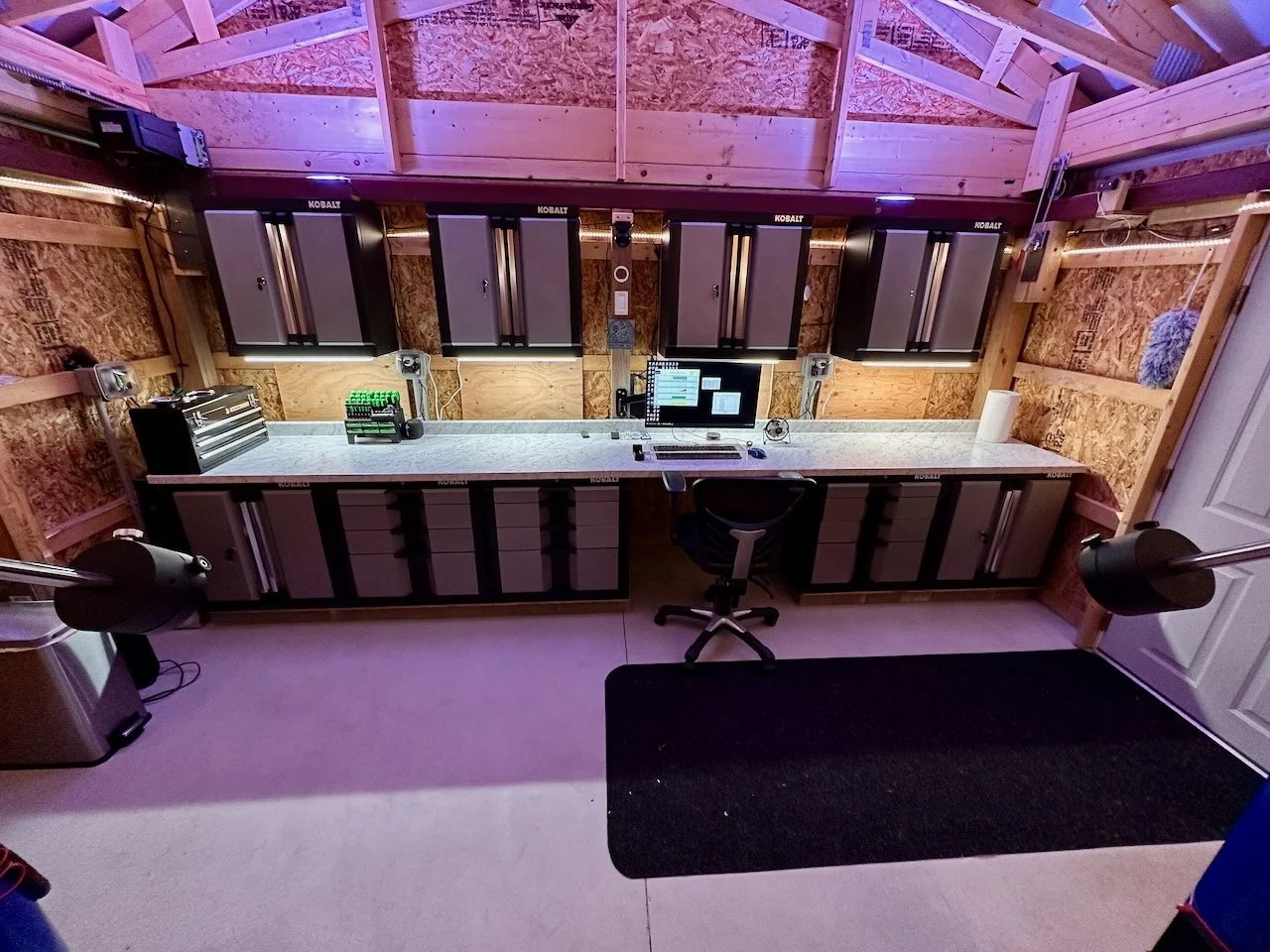
Now shown with the roof closed and the under-cabinet work lighting turned on. Tools and workspace to the left, computer area to the right. (click to enlarge)
5) Power, Lighting, and Usability
The observatory is powered with enough capacity to support the real-world loads of imaging gear, computing, and environmental control.
To accomplish this, a 180-foot trench was cut to the main house, and a 100-amp service line was run from there, up the hill, to the observatory. At the same time, three redundant eithernet lines were also run.
Because the roof opens and exposes the interior - possibly to dew in the best case, possibly to rain in the worst case- all electrical fixtures were required by code to meet exterior/waterproof requirements.

The main power panel is to the right. On the left, you can see an enclosure that housed the Mesh Router for the observatory.
Power distribution was planned around how the space is actually used—especially the fact that there are multiple platforms, Roof Control System, Weather Monitoring systems, and lighting.
At a functional level, power is run to:
the four piers (under-slab conduits),
the roof motor (dedicated 20A line),
a heater or dehumidifier circuit (dedicated 20A line),
switched white and red lighting,
outlets on each wall, with two multi-gang outlets on the north wall to support computers and tools.
An exterior outlet and an exterior porch light to support practical needs.

Here is a diagram of the electrical service to the observatory.
There are also wall outlets and an exterior outlet for practical needs.
Lighting is designed with practical operation in mind:
White light for setup and work. This includes interior building lighting, workspace
Red light for night operations — a low string of red led’s around the lower walls of the building and in the pier wells.
Environmental control and convenience details matter because they influence how often you use the facility and how smoothly sessions run.
Red LED lighting. (click to enlarge)
White lights for the observatory (click to enlarge)
6) Network and Computing Approach
A modern observatory is as much a computing environment as it is a building.
The observatory network is designed for stability and remote operation. The goal is straightforward: I can run sessions, monitor progress, check conditions, and intervene when needed without physically sitting in the observatory all night.
The observatory is wired with redundant Ethernet runs from the house, which serve as a hardwired backhaul channel for a mesh node in the building. This provides fast and stable Wi-Fi service for the entire observatory.
A mini-PC controls the observatory and runs the Skyroof and SkyAlert software.
On the compute side, I intentionally moved away from the old “laptop on a shelf at each pier” model. I replaced that with fanless mini-PCs and a workflow that assumes the systems are headless and controlled via screen sharing. I also standardized around NINA for sequencing because it makes automation and repeatability dramatically easier once you commit to it.

Four micro-PCs, one for each pier, and set up on my desk so I could configure them. These are small, fanless, and have more than enough power to handle the tasks required for running the scopes. I treat these as headless units, and connect to them from the computer area in the observatory or remotely from my Astro Man Cave.

The OC mounted on the pier.
Two Pan and Tilt Remote Security cameras allow remote viewing of the telescopes and observatory interior.
WiFi-controlled switches control power to the computers, the computer monitor, and various lights in the observatory.
This allows the observatory and the telescope platforms to be controlled from within the observatory, but also remotely - from the comfort of my Astro Man Cave back at the house.
The computing strategy is built around:
Reliable connectivity
Repeatable device control
Efficient remote monitoring and intervention
If you’ve done enough nights in the cold, the value proposition is obvious: the less time spent physically babysitting gear, the more consistent and sustainable the workflow becomes.
The key point: I can run an entire night of imaging while monitoring from inside—without babysitting the building in the cold. (In fact, most imaging nights I sleep on a sofa in my Astro Man Cave so I can check on things between “naps”. If a real problem develops, the observatory will send an alert to my phone to wake me!)
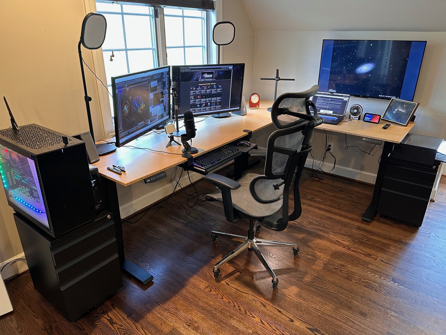
The main computer in my Astro Man Cave. I control capture sessions from here.
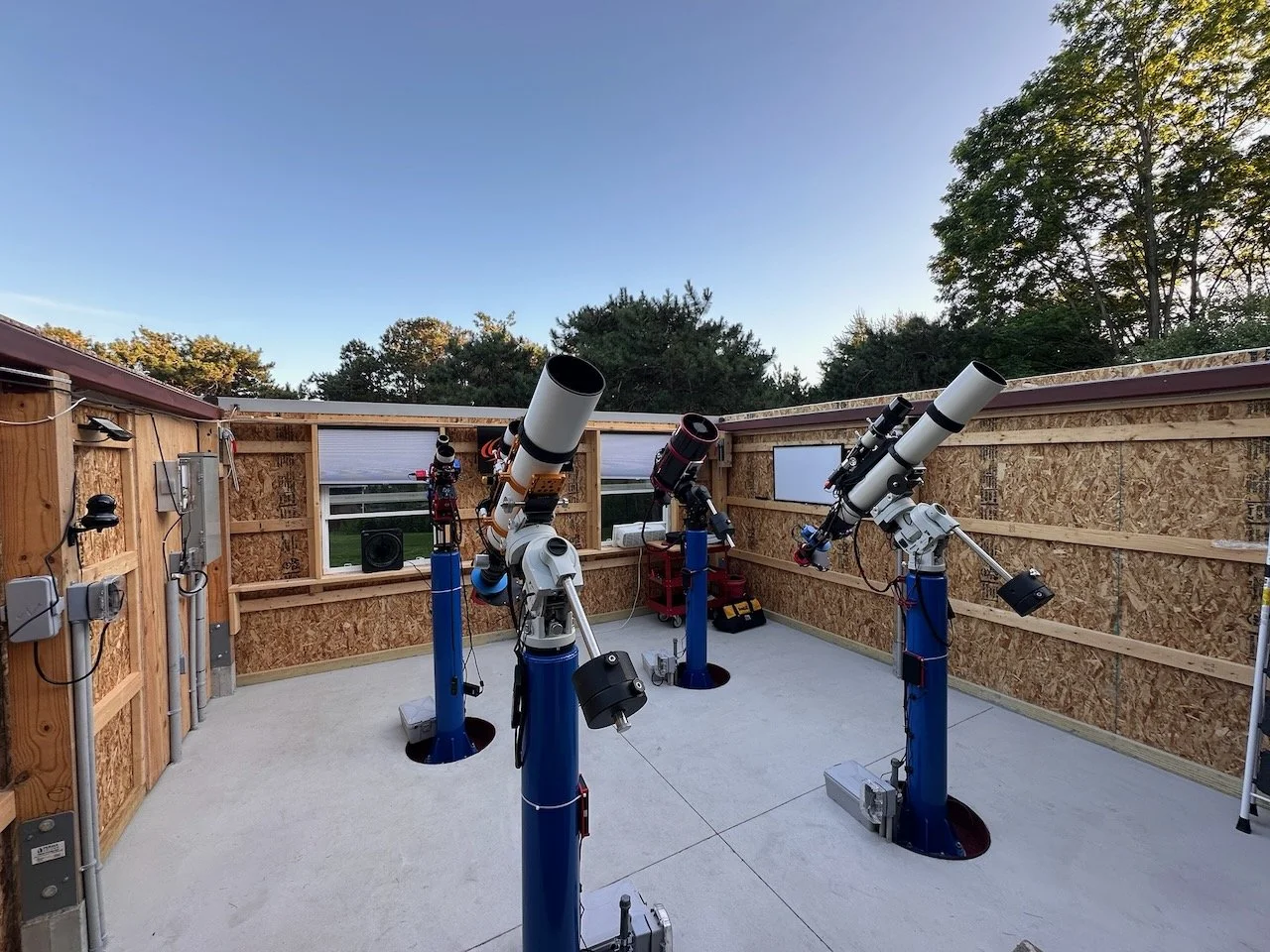
7) The Four-Pier Layout and Telescope Platform Set Up.
The observatory is organized around four isolated steel piers, one in each corner. The layout is not arbitrary—it’s designed to maximize access to the southern sky and minimize the chance of one system physically interfering with another. In general, most targets live toward the south, and longer/taller scopes can look over shorter systems when placement is done thoughtfully.
Here is the current platform placement:
SE pier: FRA400 platform
SW pier: SharpStar SCA260 V2 platform
NE pier: William Optics 132 platform
NW pier: Astro-Physics 130 platform

The four scope platforms mounted on their assigned piers. This is looking South. Bottom-Left: WO132 Platform, Bottom-Right: AP130 platform, Upper-Left: FRA400 Platform, Upper-Right: SCA260
Each platform is tuned for a slightly different job (widefield speed vs focal length and resolution), and having them permanently mounted means I can select the “right tool” for a target without reconfiguring the world.
William Optics 132 Platform
Mid-aperture refractor workhorse. Reducer/spacing flexibility.
Astro-Physics 130 Platform
High-confidence refractor for tighter framing and stable performance.
Askar FRA400 Platform
Wide-field specialist. Fast composition and large-structure targets.
SharpStar SCA260 V2 Platform
Reach + speed for galaxies. Demands tighter mechanical discipline.
8) How A Typical Imaging Night Runs
A typical session now follows a repeatable operational pattern:
How a Typical Imaging Night Runs
Each section below expands. This keeps the workflow scannable on mobile without losing detail.
1
Day Before
- Check forecast, wind risk, and dew potential.
- Select primary and secondary targets (by platform).
- Build NINA sequences: framing, autofocus, guiding, and start/stop rules.
2
Before Dark
- Open roof; verify clear travel path.
- Seasonal: pre-cool the space with fans (if needed).
- Remove caps, enable power to platforms, connect remotely.
- Quick preflight: devices connect, focusers respond, guiding ready.
3
Run the Night (Remote Supervision)
- Start sequences on each platform PC.
- Automation handles: plate solve/sync, wait for target altitude, run acquisition plan.
- Monitor exceptions only (alerts, guiding/focus drift, clouds/wind).
4
Morning Shutdown
- Sequences end: warm cameras, park mounts.
- Close roof and engage manual lockdowns as needed.
- Cap optics (check for dew), power down platforms.
The observatory doesn’t remove the need for good process—it enforces it. And that’s a good thing.
Ready for a night of photon capture!
9) Capabilities and Limitations
What it does well today
Supports repeatable astrophotography workflows with permanently mounted platforms
Provides a practical workspace for maintenance and upgrades
Enables reliable, controlled roof operation and weather-aware decision-making
Reduces operational friction enough to materially increase imaging throughput
What still limits outcomes
No Passive Roof Interlocks for Wind Security. My original plan called for Passive Interlocks for the Roof.
One operational reality of a roll-off roof is wind. When the roof is closed, the most secure approach is a manual lockdown—but manual lockdowns come with a tradeoff: to use the observatory, you must manually unlock the roof, and to leave it secure, you must manually lock it down again.
I can open and close the roof under software control, but without some form of mechanical retention, that automation alone does not protect the roof if an unexpected wind gust hits while the roof is sitting at an endpoint.
To address that gap, I planned on implementing passive roof interlocks. The idea is simple and purely mechanical: when the roof reaches the fully open or fully closed position, parts of the roof assembly automatically engage mating features on the walls. In other words, the roof “captures” itself at the endpoints without me having to get involved. This provides meaningful resistance to uplift and lateral movement—enough to make automated operation more practical.
These passive interlocks are not a substitute for a proper manual lockdown in major wind events. They are a middle ground: less secure than a full manual lock, but far better than leaving the roof unrestrained, and they preserve what makes the system valuable—being able to move the roof under automation with reasonable confidence that it won’t be vulnerable to a sudden gust.
These would passively lock the roof in place when it was fully open or fully closed. The design I had turned out to be unworkable. So I need a new one. Until then, I cannot fully automate roof opening, and I have to watch the winds carefully. The good news is that the winds around the observatory are always much lower than around other areas of the property. It seems to be protected by the trees. I opted for the mechanical anemometer for the Sky Alert system, and if the winds pick up, I can close the roof.
Weather. No observatory removes the fundamentals:
Weather still drives the schedule
Seeing and transparency still set the ceiling on resolution and depth
Dew and temperature swings still require good process and equipment discipline
And like any serious build, there’s always a list of incremental improvements—but the observatory is now a functioning facility, not a construction experiment.
10) A Name and A Sign
It took me a long time to come up with the name Whispering Skies Observatory. I put more time into it than I really should have. I liked this name because it captures a theme I find compelling in Deep Sky astrophotography: the idea that images are formed by a thin stream of photons that have traveled for thousands or millions of years before landing on our camera sensors. The skies whisper to us, and we must listen carefully to “hear” their message.
The sign for the observatory has its own story, but the short version is that I had it designed by ChatGPT, which seemed to have a lot of trouble spelling the words in the graphics, but I was able to correct that. I rather like the final sign, and at the end of the day, I was the only one who had to!

The design for the Observatory Sign.
11) Lessons learned: What I’d Repeat and What I’d Change
If I were advising someone building a similar observatory, the short list would be:
Design around workflow, not just structure.
Over-invest in roof mechanics and long-term stiffness. Treat roof mechanics as a long-term reliability system, not a convenience feature.
Plan water management early and conservatively—drainage mistakes are persistent.
Reduce moving roof mass wherever practical; weight matters.
Treat power and network as first-class systems, not afterthoughts.
Make space for real work: cabinets and countertops are not “nice-to-haves” if you intend to maintain and evolve multiple platforms.
Built-in safety: a closed roof should also be secured, not just “shut.”
Lessons Learned
Lawn Restoration. Plan for lawn restoration in your budget - this kind of build will tear things up, and it can be costly to repair.
Building Contracts. If you are working with a contractor, I would make sure your contract includes time goals and penalties in writing. The contractor I used has some very skilled workers, but I was a small job in a sea of bigger jobs, and workers were often pulled from my job for more important ones. So the construction took MUCH longer than I ever guessed.
Lockdown Your Passive “Lock Downs”! I had some ideas around this that could have been done early in the build process when the welder was on site. But we did not get to it during the available time we had with him. Later, he took on a big job that made it unavailable, so we came up with a plan that would work without a welder. We chose one that could be added on after the building was done. But this plan has hidden flaws and is not viable. I now need to come up with something new. It hasn't been a big deal so far, but there is an automated part I can no longer access without it. I should have prioritized this feature up front. The builder suggested that the welder was good at working details like this, so we left it loose. This was a mistake.
12) Video Overview
A friend of mine shot a video overview of the Observatory that was then presented at a session of the Rochester Chapter of IS&T.”
13) Related Links
Optional deep dives that complement this overview (kept distinct from the earlier link section).
Electrical Plan and Implementation
How the 100A service, circuits, lighting, and pier feeds were planned and installed.
Computer and Remote Operations Strategy
How I moved to headless mini-PCs and standardized the workflow.
Piers and Scopes Layout
Why the corner layout works and how the platforms are arranged.
Drainage and Lawn Restoration
Why I skipped gutters and used perimeter drainage to manage runoff and snow/ice realities.
Conclusion
This project was a long time coming and took quite a bit of effort to complete. After using it since May of 2025, I can tell you that it was all worth it.
If I get a night that just opens up, I can be ready in 5 minutes.
If a good night turns bad, I just shut things down - it takes me 5 minutes.
The overhead of setting up and aligning equipment and taking it down again has been eliminated.
Having the observatory, which has greatly enhanced my access to the sky, is just as beneficial!
I completed 25 imaging projects from May to November, and my average time on target has increased substantially! I had some images with integration times over 30 hours, and that is a big change!
This is my dream observatory, and I can’t wait for all of the imaging I will do with it during 2026 and beyond!