
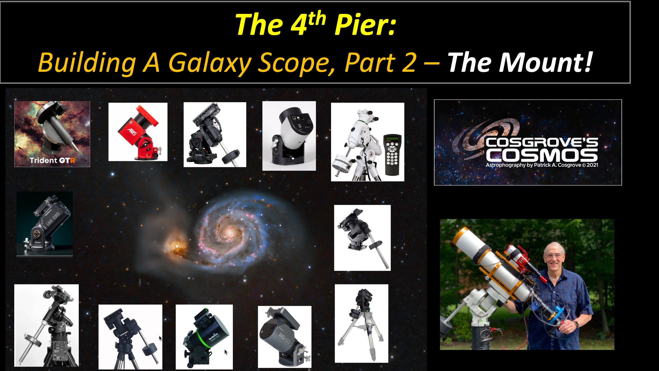
The 4th Pier: The Sharpstar SCA260 V2 Platform Ver 1.0
Date: May 3, 2025
Sharpstar SCA260 V2 Platform Ver 1.0

Specs + Performance
| Metric | Value |
|---|---|
| Effective focal length Aperture 260mm | 1300 mm f/5.0 |
| Image scale Pixel 3.76µm | 0.60″/px 4.2 px/FWHM @ 2.5″ |
| Field of view (W × H) Sensor 23.5×15.7mm | 1.04° × 0.69° 62′ × 42′ |
Sampling
Oversampled
4.2 px/FWHM · target ~2–3
Guiding
Tight 1.56×
Guide scale ≈0.93″/px (OAG) · ≤3× is generally fine


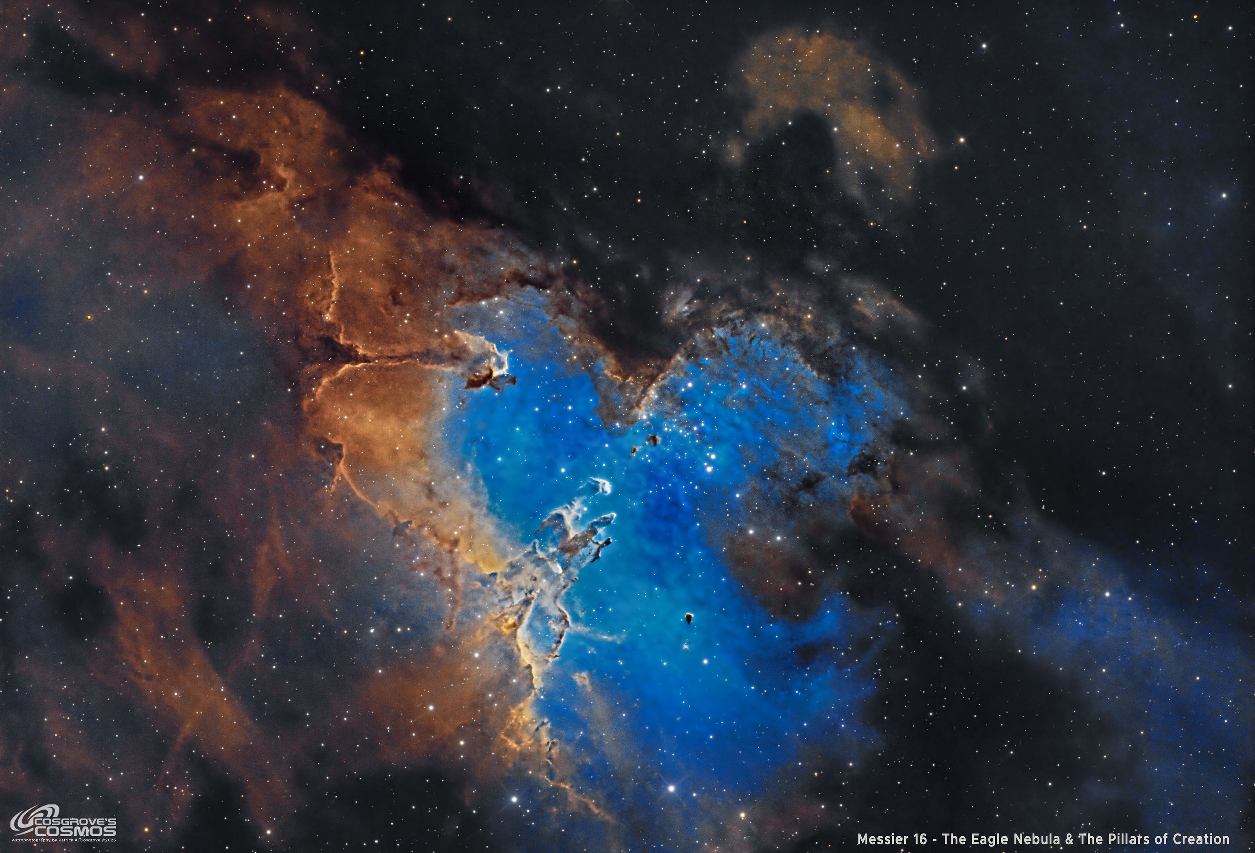

Table of Contents Show (Click on lines to navigate)
Leading Up to This Post
I recently shared two gear posts that were exploring what kind of platform I should build and mount on the 4th Pier of my observatory. The first post dealt with my options, where I settled on what I wanted for an Optical Tube Assembly. It can be seen here:

Click to go to post.
The Optical Tube Assembly will consist of:
Sharpstar SCA 260 V2 (1300mm @ f/5) Scope
ZWO ASI2600MM-Pro Camera
ZWO EFW 7 x 36mm
ZWO AOG-L
ASI 174MM-Mini Guide Camera
ZWO EAF Focus Motor
The second post dealt with the mount selection. This can be seen here:
Click to go to post.
The mount chosen here was the IOptron CEM70.
Now it was time to put this all together!
Video Companion
This post has a video companion that covers much of the same material but sometimes you get more from the video and sometimes more from the web post, so I provide both!
Placing the Orders
My original intention was to assemble the scope and install it sometime later in the year. But with all of the nonsense with tariffs, there was a chance that waiting until later in the year would mean either availability issues or significantly higher costs.
So, my wife (despite having just supported the construction of the observatory!) suggested we buy everything now and avoid this.
Who am I to say no to this?
(As one of my Astro friends put it - “See, the Tariffs are already working!”)
So I placed my order, and things began to arrive. Let’s start with the Optical Tube Assembly.
The Telescope
The Sharpstar SCA260 comes well packaged, but with no documentation whatsoever. It has a warranty card, two Allen wrenches for doing collimations, and a Cheshire Eyepiece for that purpose as well.
There is no visual back, so you must provide that. When using a Cheshire Eyepiece, it's important to ensure that it is held concentrically in the holder to maintain its center positioning. Fortunately, I had an extra William Optics Rotolock, and I used this as the visual back.
I also noticed that the focuser was not sitting squarely on the scope—it was rotated to one side. I tried twisting it, but it would not move. I did not want to force it, so I contacted Agena Astro, where I bought it. They checked with the technicians and advised using a strap wrench to just turn it a bit. I did that, and problem solved!

The packaged scope

The Front end showing the secondary mirror holder

The back view with provided Cheshire collimation eyepiece in the Rotolock visual back.
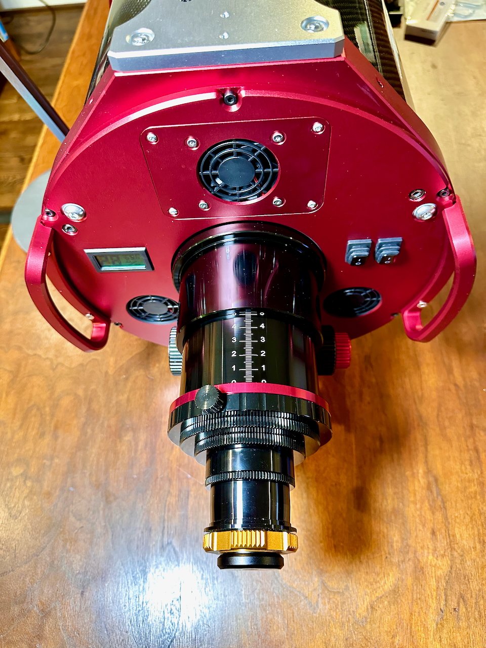
Top view of the heavy duty stock focuser.

Just out of the box!

My William Optics Rotolocks that I will use for collimation.

This shows how the focuser came crooked on the scope. It took a strap wrench to straighten it out.

The Top Mounting Plate.
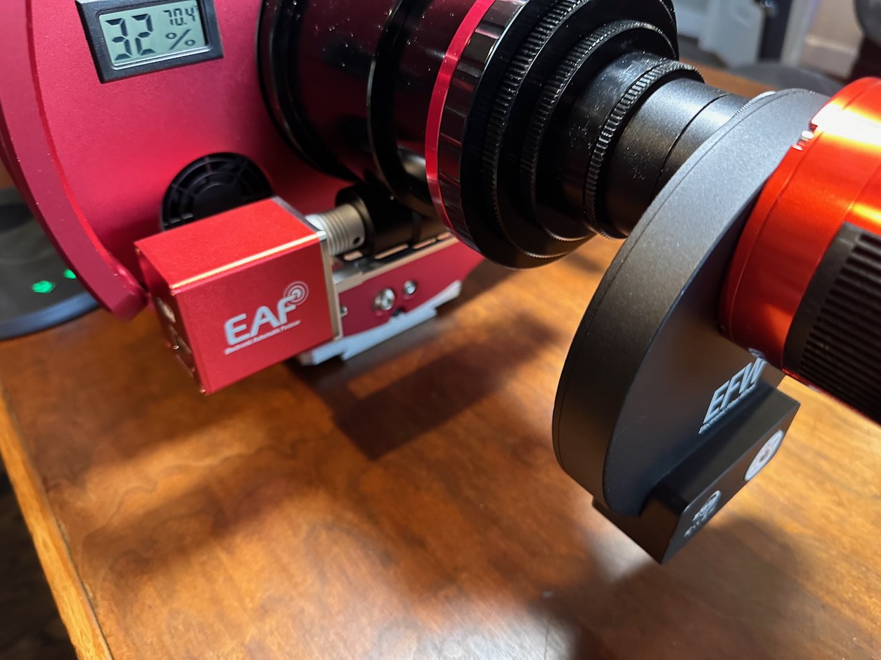
Mounting the ZWO EAF Focus Motor
I had seen that the ZWO EAF Focus Motor was compatible with the SCA260. But when you try to install it, the carry handles mounted on the rear of the V2 scope get in the way.
So I removed one handle, and this allowed me to mount the motor and coupler.

The EAF can’t be mounted with the handle on.

So we took it off!

It fits fine now!
Next, I had to mount the Bracket. There are two holes designated as available for mounting focus motor brackets on the bottom of the focuser. I identified them and thought that I would have no trouble mounting the EAF bracket with two screws.
However, the bracket only spans one of the holes or the other. So I was forced to mount it with one screw. I figured that if I needed to, I could always use the hole for the focuser lock screw, and used a shorter bolt. But I found that one screw provided a solid mount and I was able to go ahead and re-install the carry handle. I still had enough clearance for the USB cable.

Coupler attached.

One screw to hold them all!

Fitting the bracket.

EAF mounted, handle back on and USB cord fits!
Mounting A Temporary Camera Rig
When I mounted the EAF, I did not expect to finalize the camera setup until much later in the year. But I wanted to do something with the scope. I had an old ASI1600MM-Pro camera with a 1.25-inch filter wheel that was not in use, so I added that one as well. Once I got a mount, I could install this OTA and test some things out.
And that is just what I did. Some of the images in the next sequence will illustrate this.
However, when tariffs, or threats of tariffs, were introduced, that changed everything.

Temporary installation of an old ASI1600MM-Pro Camera stack.
Another view.

Back view.
Installing the Mount
Shortly after I installed the four Piers in my new observatory, my New IOptron CEM70 mount arrived. I installed that using a modified IOPtron Top Pier Plate. Knowing that the scope would be on the heavier side, I had purchased an additional large counterweight for the scope.
So I bolted the scope onto the pier, adjusted for our local latitude, and then added the counterweights.
With that, I was not ready to install the scope.

The CEM70 mount as it arrived. Sitting on the lower box is my Top Pier Plate that has been modified to work with my steel piers.
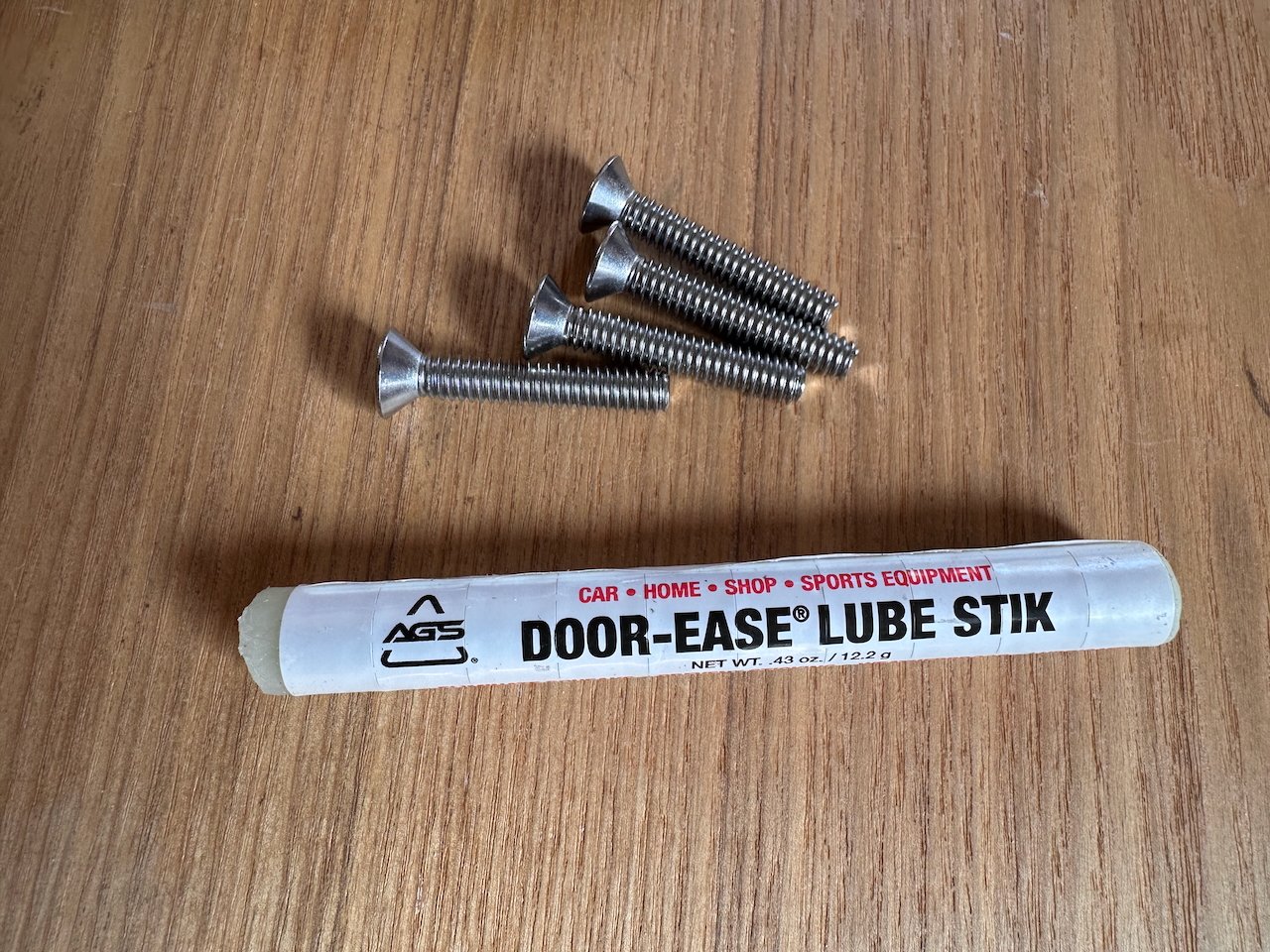
Befre bolting down the Top Pier plate, I used some stick lube to prevent binding.
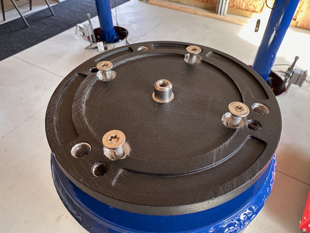
The bolts - part way in.

The mount ready to go.
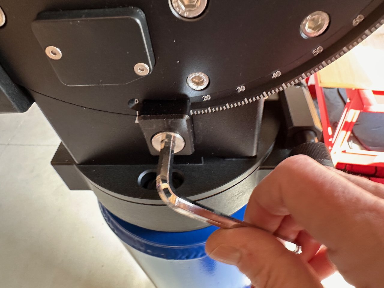
Loosening the Alt lock so I could set the correct value for my location.

The mount, ready for mounting!

Now ready for the scope.
Installing the Scope
I then carried the scope up the hill and placed it on my wheeled cart. This cart was critical when I used to set up in the driveway, but I've also found it very handy in the observatory. I can put OTAs on it and wheel them around nicely. It’s worked out great!
This scope is hefty for a single person to handle, so I did what I have done in the past: I put a Losmandy dovetail clamp on the rail at the end so that the scope could not slip through the mount as I tightened it on.
Once mounted, I balanced things roughly, and then I was ready to wire things up and get the scope into play, at least on a limited basis!

Using my astro cart to wheel around the OTA>

The clamp mounted to the end of the rail.

A Losmandy dovetail clamp I will be using.
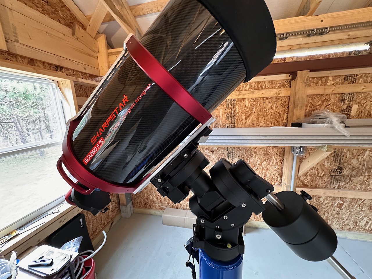
Telescope now mounted.
I used the old camera to test out the EAF and to do NINA 3-point Polar Alignment. So that part was good.
But as a trade war looked like it was about to break out between China and the US, my wife thought it would be smart to move on the camera and I certainly was not going to say no to that!
New Camera Assembly
The critical components for the Camera Assembly showed up and I was raring to get started putting them all together.
After all - this was not my first rodeo. This is the third such configuration that I have put together. Sure, it is tricky:
You are dealing with unframed filters that need to be held onto the filter wheel with rings held down with microscopic screws.
You are bolting the Camera and the OAG directly to the EFW.
Been there. Done that. Got the T-shirt!
Except for the subtle and creative way that I completely screwed this assembly up!
Follow along and see if you can spot my Brain Fart!
The general plan was to:
Remove the tilt-plate from the camera and bolt the EFW directly to the camera
Then bolt the OAG-L to the removable EFW Plate.
This would all go together like this:
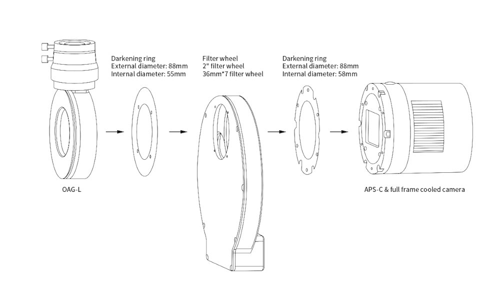
The Assembly plan (from ZWO)
A Place to Work
I will be doing this work in my Astro Man Cave, but before starting, I did a few things:
I wiped down the desktop and local surfaces with a damp microfiber cloth to remove loose dust.
I wore a hat to keep my hair from falling into the work area
I wore a mask to prevent drool and spit from flying around
I wore gloves for most operations.
I had an air bulb and a camel-hair brush to remove any dust visible on the filters or camera cover glass.
Keep in mind that none of this will likely help eliminate dust from the filters and camera, but I felt I had to at least try.
Mounting the Camera to the EFW
First, we need to take the tilt plate off the camera. We are doing this because we will be bolting the EFW right to the body of the camera.
Would removing the tilt plate be an issue? Not really—a new tilt plate is included on the OAG, and we can adjust it if needed.

Loosening the screws holding the tilt plate on.

Removing the tilt plate.
Next, we need to disassemble the EFW. This is done by removing the series of screws that surround the EFW. I am using a small powered precision screw driver here, which makes this quick work.
Once I have the cover off, I am going to remove the filter wheel itself. This is done by removing three small screws near the center of the wheel.

Using a powered screw driver to remove the FEW cover plate.

Removing the three central screws that allow you to remove the wheel itself.
Cover plate removed.

Removing the wheel.
With this done, we can bolt the camera directly to the back of the EFW using the threaded holes provided. Screws came with the EFW for doing this.
Before doing this, you need to put a light gasket between the two. ZWO provides this to help prevent light leaks and to generally make a precise and fussy operation more complicated and fussier, as you need to get everything lined up to make it all work.
(I will be doing a video showing this operation. I will cut out all of the parts that make me look like an uncoordinated oaf and try to make it look easy. But rest assured - easy, it is NOT!)

Placing the light gasket on the camera before bolting the EFW to the camera.

Putting in the first screw.

All Screws are now in.
Mounting the OAG to the EFW
The next step is to bolt the OAF to the back of the cover plate.
To facilitate this operation, you will need to remove the tilt plate on the OAG. This will provide you with better access to the holes required for mounting the two items together.
Fear not, as ZWO has included yet another light gasket here, making this another exercise in frustration. I used many four-letter words as I was performing this operation. However, in the end, I managed to complete it.
The tilt plate can now be reinstalled.
Finally, I did a dry fit of the OAG plate and the Camera/EFW body. I checked where the prism was located compared to the camera, and saw that it was too far down and was shadowing the sensor a bit. So I losened the shown screw and pulled the prism up a bit.

Removing the title plate from the OAG-L.

Bolt the OAG-L onto the EFW plate.

Placing the light gasket onto the EFW plate.

Add the tilt plate back on.

Checking the positioning of the prism - its too low right now.

Loosen this screw to adjust prism positioning.

The new position should work well.
Installing the Filters into the Filter Wheel
Have you spotted my screw-up yet? Nope? Ha! I haven’t done it yet. But, pay attention - it’s coming….
This next step is a doozy. You need to place the filters into their wheel slots, then install seven retaining rings.
If you have the hands of a surgeon, you should have no trouble!
However, if you have a handful of fat fingers that feel like Vienna sausages when you are trying to do delicate work, this part might be a bit fussy.
Putting the filters into the right slot is easy enough. You have to open each filter package and carefully set them into the slot you want. I used the same sequence that most people use:
Slot 1 = Lum
Slot 2 = R
Slot 3 = G
Slot 4 = B
Slot 5 = Ha
Slot 6 = O3
Slot 7 = S2
The LRGB filters were ZWO filters. They were once a pain to install, as they only had anti-reflective coatings on one side, and you had to determine which side was facing the right direction. However, with the second generation of these filters, they apply AR coatings to both sides, so it no longer matters. These filters are very thin and fit easily into the wheel.
For my Narrowband filters, I am using Astronomiks 6nm cut filters. These also have AR coatings on both sides; it does not matter which way you put them.
They are noticeably thicker than the ZWO filters.

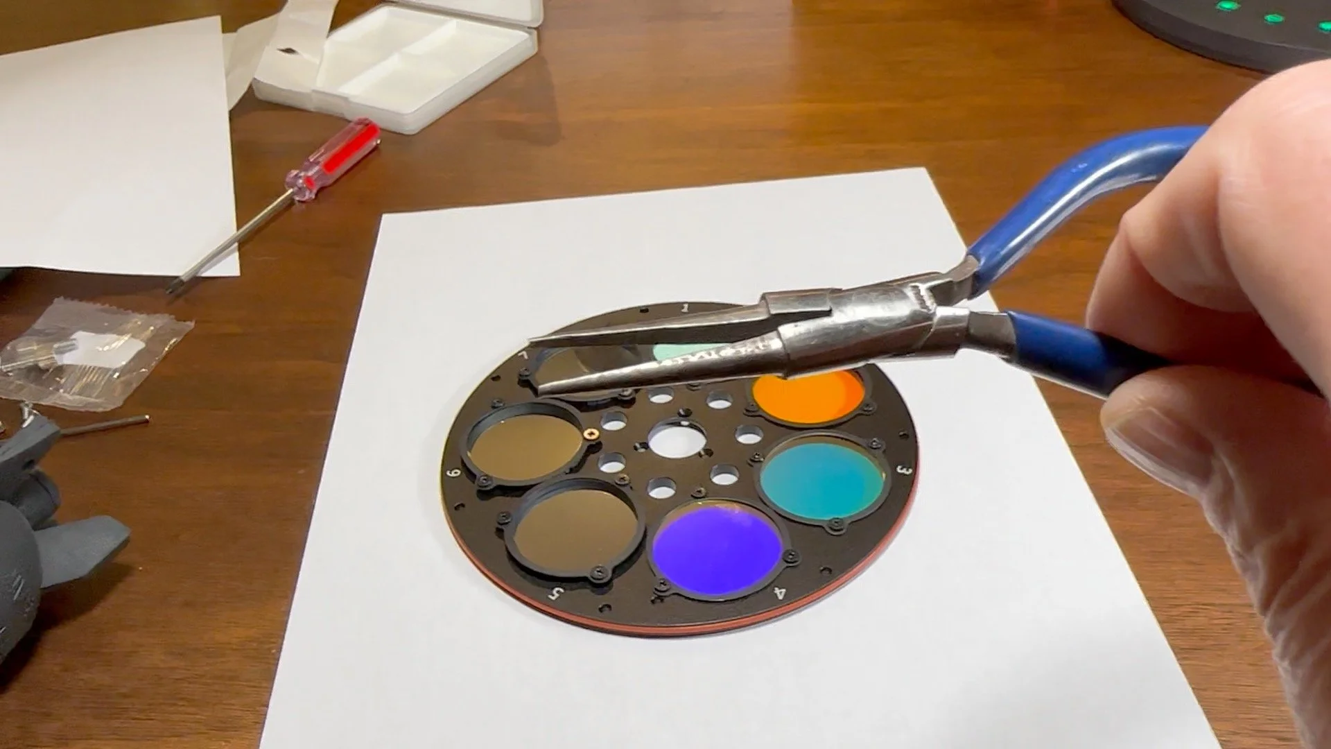
The wheel - right side up. Note you can read the position numbers.

Filters placed in their slots.
Next, you need to mount the retaining rings. These are blackout rings that not only hold the filters in but also mask off their edges to prevent any reflections from their sides, since they are frameless.
Each ring is held in my three microscopic screws. That means you have a total of 21 of these little bastards to get in. I found using the skinny needle-nosed pliers to help quit a bit. You really needed them when putting the retaining rings on the Astronimiks filter, as they were so thick.
But I got through it. If I can do it with my Vienna sausage fingers, you can do this too!
Just go slow and be careful!

The retaining rings and screws,
Using these very fine needle-nose pliers helped get these little screws started.

Filter and retaining rings in place.
In this image, you can see the wheel, along with its numbered slots, and the filter retaining rings. Please note this fact.
Reassembling the EFW
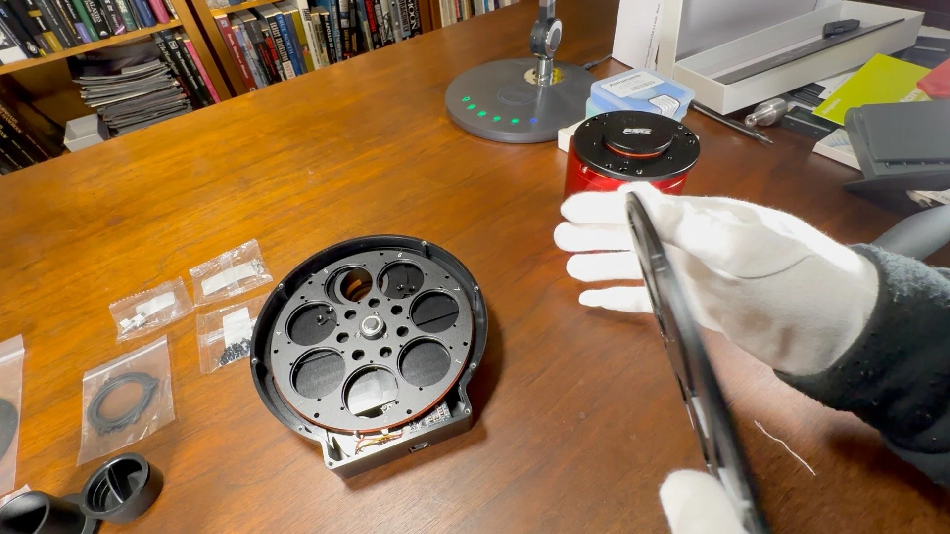
With the filters mounted, we can remount the wheel into the EFW housing.
Just drop in the wheel and screw it back in with those three tiny screws you took out.

Putting the wheel back in the EFW. I DID THIS WRONG! Note the slot numbers are no longer visible. I did not know it at the time, but this was a dumb mistake to make!
Notice anything?
Can you see the slot numbers?
How about the retaining rings?
No?
That’s because I put the wheel in BACKWARDS!!
I did not know it at the time. I was as happy as a clam. Guess what happens when you put the wheel in backwards? We will see. Stay tuned.
Then, replace the lid on the EFW and secure it with bolts.
Satisfied with that, I installed the ASI174MM-Mini guide camera, and the Camera assembly was complete.

The assembled Camera Stack.

Looking down it’s throat.
Installing the Camera on the Telescope
With the camera assembly ready to go, I took it up to the observatory and replaced the ASI1600MM-Pro assembly with the new camera rig. Then I went about wiring things up.
I added a Pegasus Astro Pocker Powerbox Micro and a 7-port USB Hun powered by 12V.
I placed the environmental probe on the scope's back plate.
I also added a DEW strap to put around the base of the mirror on the outside of the scope.
Power went to an Anderson Powerpole splitter:
One line went to the mount.
One line went to the main DC distribution feed.
This then fed the camera, the SCA260 Fans
One line went to the camera
One line went to the Pocket Powerbox
This fed the dew heater trip and the USB hub.
For USB, I ran the main line to the USB Hub. This then fed :
the camera
The camera hub supported the EFW and the Guide Camera
The Mount, whose hub supported
the EAF
All of this was cable wrapped to neaten things up.

The mounted camera, showing the initial cable management.

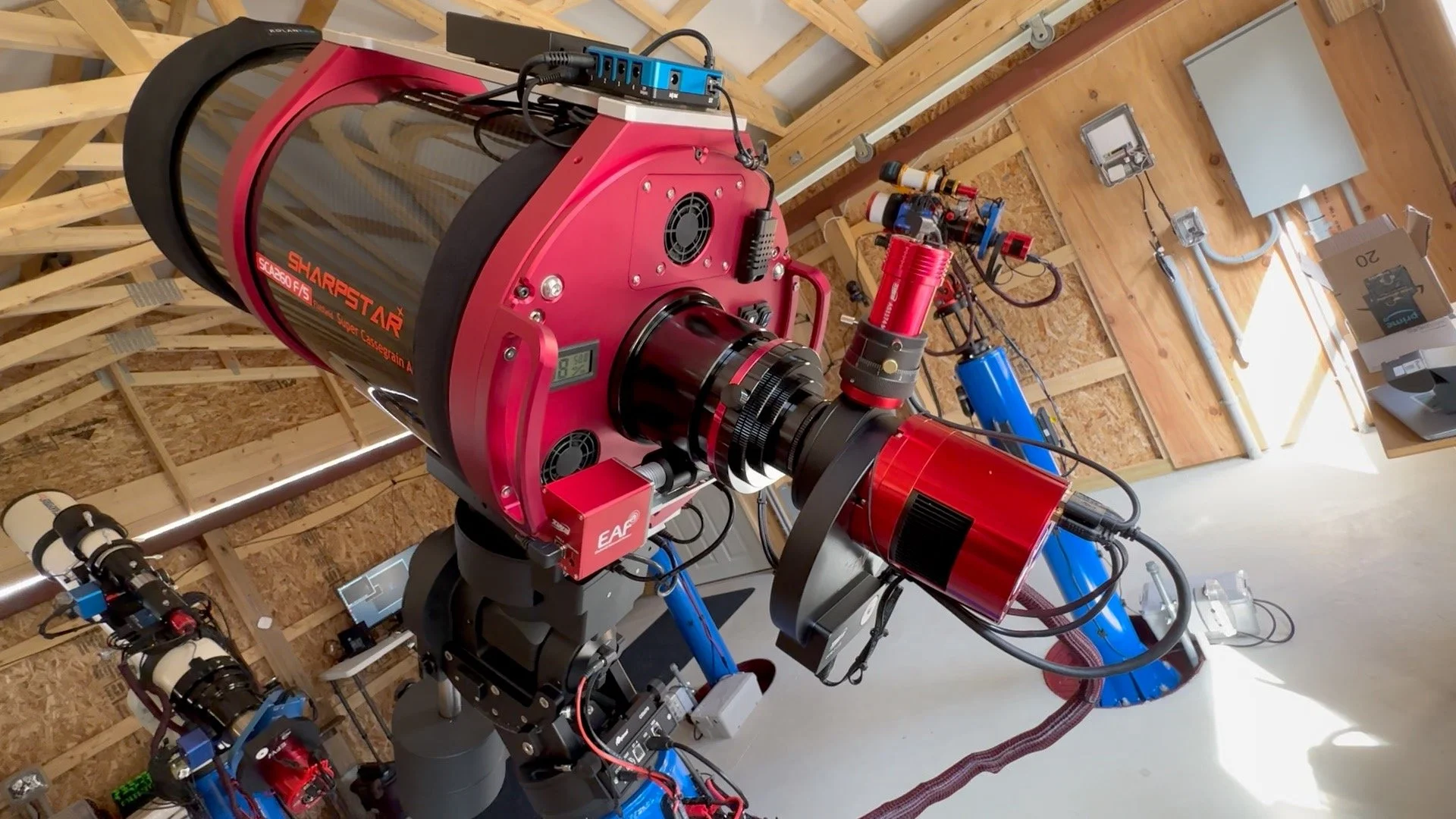
A view of the whole scope.

A closeup on the camera.

The Pocket Powerbox Micro and the 12v powered hub.
The EFW Problem Discovered
When we finally had our first clear night, I went out to set up the scope. The first task was to achieve focus on the camera.
Usually, this is simple. But tonight I could not see any out of focus star images and could not get the focus set. Out of desperation, I shined a flashlight down the tube and the camera image on the screen clearly showed that the EFW was between filters! Something was wrong. I used NINA to change flter to the L filter.
Looking at the camera on loop mode, I finally saw out of focus stars - that suddenly got progressively dimmer and then went away completely - and then came back again!
I realized the filter wheel was just spinning.
I pulled the camera and tool off the EFW plate. When I commanded a filter change, the wheel just spun in place! I then hooked it up to ASIStudio and saw similar behavior. I did this because I thought I had a bad unit, and ZWO wants to know what it does when connected to its own software.
I changed filters, and it spun the wheel completely and then stopped. The driver no longer showed filter position options. I then tried to recalibrate the EFW, and it failed with an error.

Getting ready to flip over the filter wheel in my observatory.
With this in hand, I went back to Agena Astro to ask for either help or a replacement.
They were willing to replace it thinking I had a bad sensor or sensor board, but they sent me a doc with pictures showing me what to do and I asked that I give it a try first.
I looked at the document image and my video of the problem with the cover off, and immediately realized that I had installed the wheel backwards.
If you install the wheel backward, it will fit and spin just fine. But in this orientation, the holes on the wheel that the IR sensors look for no longer line up!
I went back out to the observatory and flipped the wheel. Suddenly, everything started to work!
I went back to Agena Astro with the Following Note:
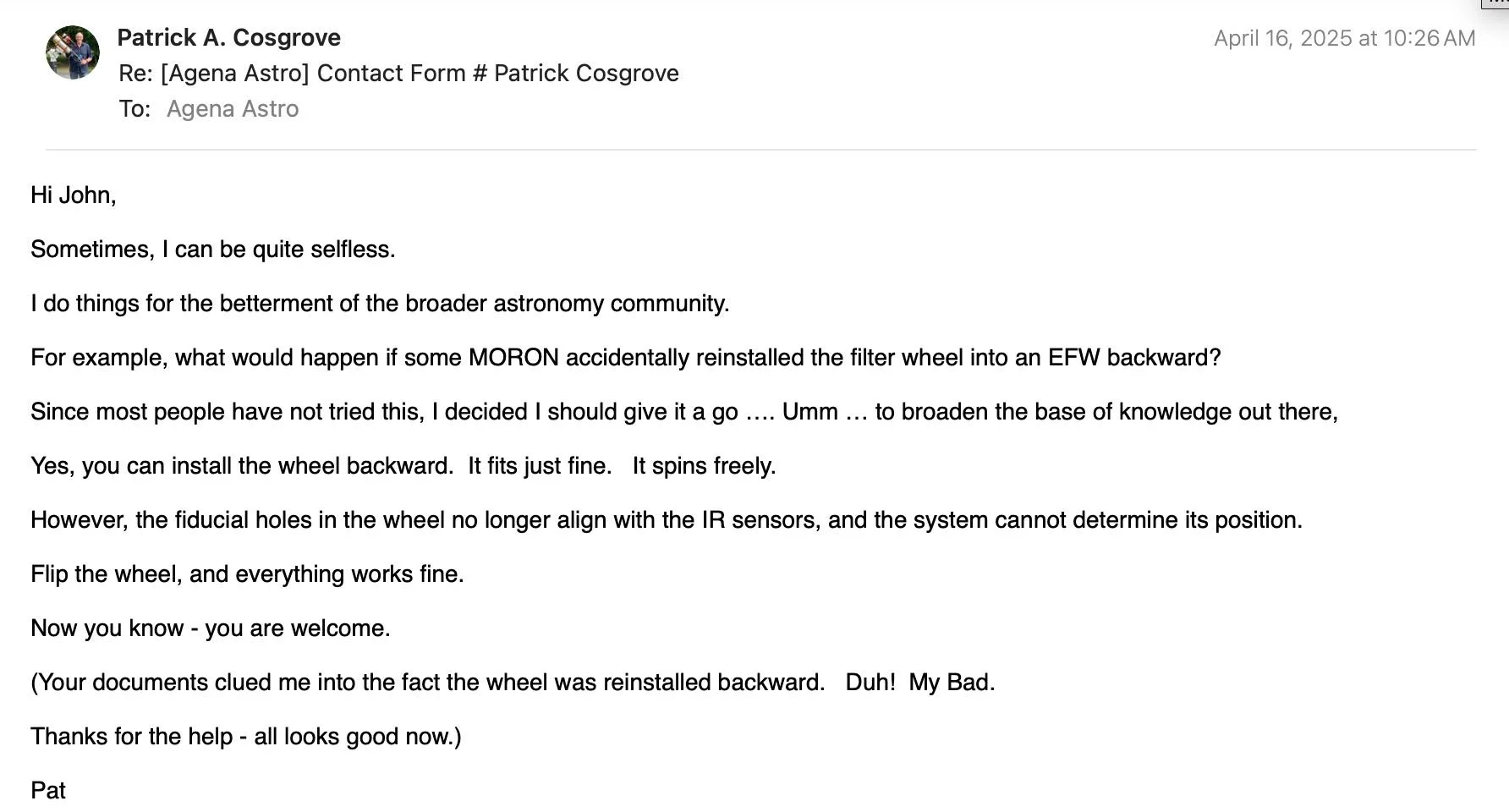
He took it quite well, given that I he had been trying to help for for a couple of days…

With this corrected, I went on to get everything set up.
When I got to the OAG, I also needed to focus that camera. Again, I had a problem.
I could not see any stars! The camera comes with an extension barrel attached. I tried removing this and lo and behold - Stars! Focusing and setup proceeded from there.
First Light
After all of this nonsense, I finally had a chance to try it out on a nice, clear night. I
n some ways, this was very premature. I still did not know how well the scope was collimated,, but I figured I would give it a go anyway.
I chose M106 as a target and shot LRGB and Ha images of it.
I did find that I had a problem with the Meridian Flip, which happens when you completely forget about setting this critical piece up!
I also found that I needed a new way to do flat calibrations. I bought a large A1-sized LED trace panel and mounted it onto the wall of the observatory. I pointed the scope at it and shot a Flat series using the FlatWizard in NINA.
The images came out with the flats overcorrected, a problem that took me a few days to sort out. I will write about that adventure in its own post, so keep an eye out for that.
I also discovered problems with my Ha Flats, seeing some nonlinearities in my flat source, which I must also deal with.
Below is a 1-hour integrated Lum frame with almost NO processing.
Lots of nice detail there and I can’t wait to process this image and see the final result!
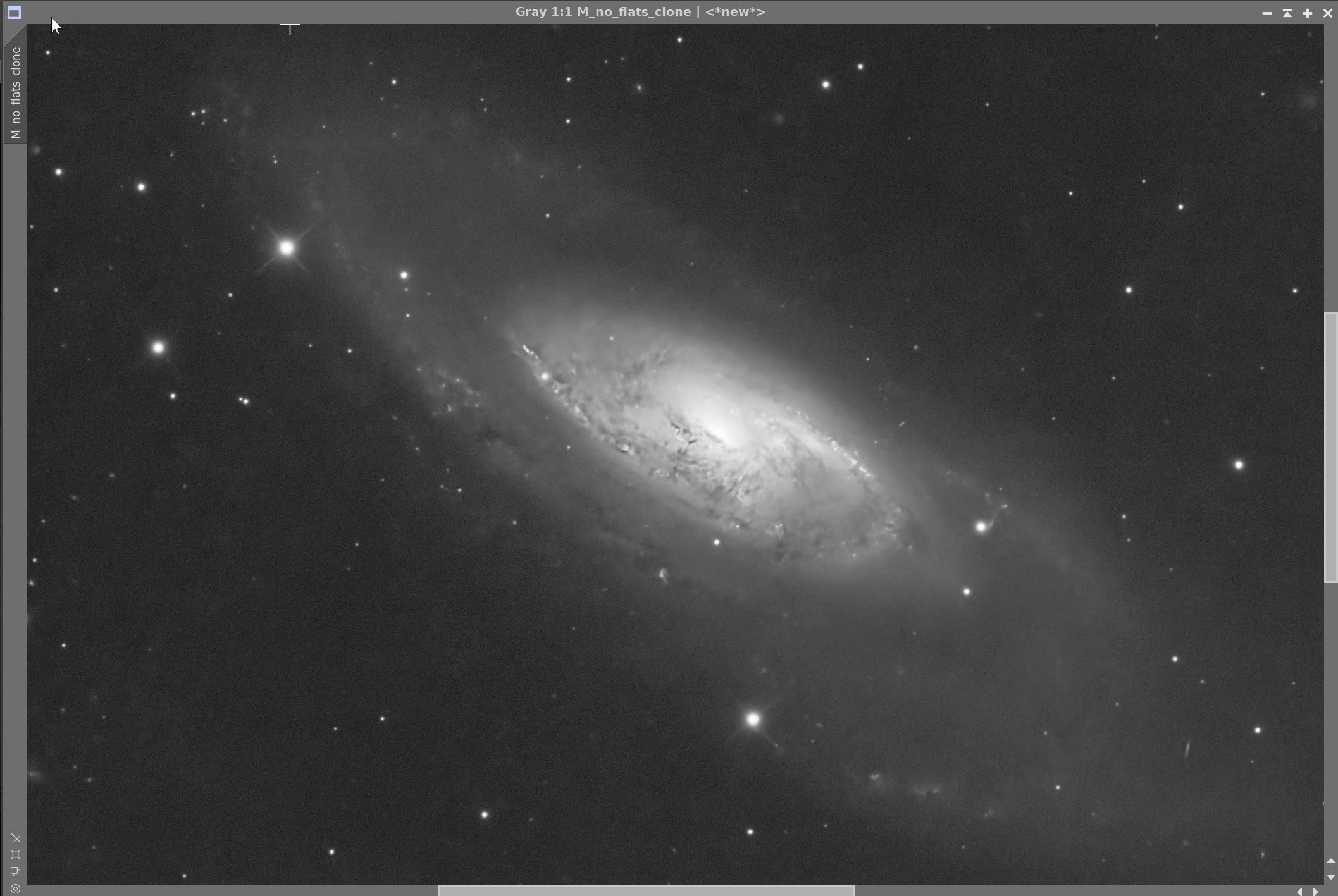
I-hour Lum frame integrated and little processing done.
Initial Assessment:
As stated, I still need to verify collimation. The collimation through the Chesire eyepiece looked good. A bright star out of focus also looked pretty good. However, I will be the first to say that I am not experienced in these judgments and will need to follow up on this.
I also have an issue with my Flat light source. I need to diffuse the light from this and integrate over a longer time for the broadband filters.
The initial images, however, seem pretty detailed, and the stars seem reasonably formed and look OK.
The IOptron CEM 70 tracking, in general, is running about 0.58 RMS, but I am seeing some guiding spikes every so often that are less than desirable. I need to double-check my 3D balance and make sure I have not cable-dragged getting involved here. I did have to throw some subs out for tracking, so something is going on here that I need to understand.
I now have about 10 hours in HaLRGB for M106, my very first image. Once I process that data, I can say more about this scope's initial performance, but so far, things look promising indeed!
Conclusion
The First Version of this telescope platform is complete and ready for use! I will be documenting any changes made to this platform so I can assign each image done with it to the version of the platform used for it!
The Final Version 1.0 Configuration:
Scope: Sharpstar SCA260 V2 260mm f/5.0 Special Cassigrain Astrograph
Focus Motor: ZWO EAF 5V
Guideing: ZWO OAG-L
Mount: IOptron CEM70
Tripod: Custom Steel Pier with modified IOptron Top Pier Plate
Camera: ZWO ASI2600MM-Pro
Filter Wheel: ZWO EFW 7 x 36mm - Second Gen
Filters: ZWO 36mm ZWO LRGB Gen II, Astronomiks 6nm Ha, OIII,SII
Guide Camera: ZWO ASI174MM-Mini
Dew Strips: Dew-Not 140 cm Heater strips for Main Scope base
Power Dist: Pegasus Astro Pocket Powerbox Micro
USB Dist: 12V powered USB Hub
Polar Alignment NINA 3-point Method