
Askar FRA400 Platform Version 3.0: A New Camera and a Motorized Cover
Dates: Feb 16, 2026 - Now
Viewing note
This post is table-heavy. I’ve made it work on smaller screens where possible, but it’s most readable on a full-size PC display.
Askar FRA400 Platform Ver 3.0

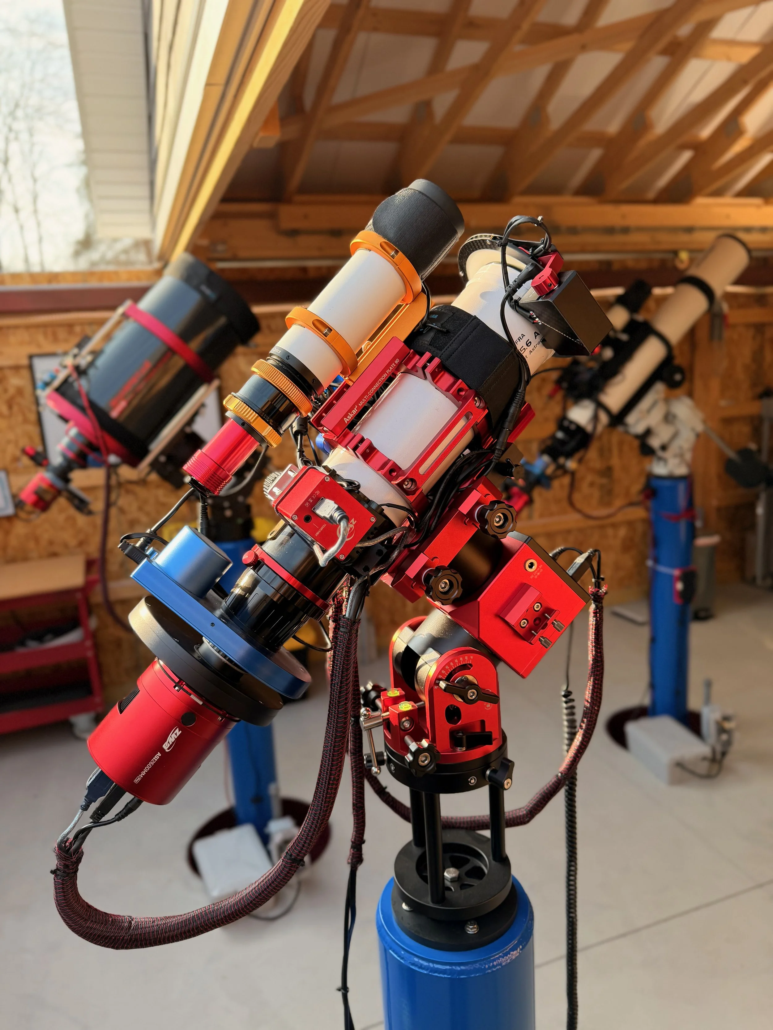
Specs + Performance
| Metric | Value |
|---|---|
| Effective focal lengthAperture 72mm | 400 mmf/5.6 |
| Image scale Pixel 3.76µm Updated | 1.94″/px1.29 px/FWHM @ 2.5″ |
| Field of view (W × H) Sensor 23.5×15.7mm Updated | 3.36° × 2.25°202′ × 135′ |
| FOV area Computed from W×H (sq°) | 7.56 sq°≈ 27,200 arcmin² |
| Diffraction limit Dawes (116 / aperture mm) | 1.61″Theoretical (seeing usually dominates) |
| Guiding scale + ratio ASI290MM (2.9µm) @ 200mm guide scope | 2.99″/pxGuide:Imaging ≈ 1.54× |
Sampling
Undersampled
1.29 px/FWHM · target ~2–3
Guiding
Tight 1.54×
Guide scale ≈2.99″/px · Guide:Imaging ≈1.54× (lower is easier)
[Place Holder for example images taken with this scope]
Table of Contents Show (Click on lines to navigate)
Overview
While the clouds of Winter block my night skies, I wanted to do some planned platform upgrades and get things ready for clearer skies to come.
This version of the platform consists of:
Updating to a more modern astro camera
Adding a motorized telescope cover with a flat light source!
Platform Change Summary
A New Camera
Three of my telescope platforms feature ASI2600MM-Pro cameras, while my FRA400 platform still has an older ASI1600MM-Pro camera.
I’ve taken some really nice images with this older camera, but it was clear to me that the 2600 series was a significant improvement. The APS-C sensor has about the same pixel size but is larger, resulting in a wider field of view. It has a very low read noise and a superior quantum efficiency. There is no measurable amp glow, and there are no microlensing reflection artifacts on bright stars.
The 2600 series camera is just better than the 1600 series in so many ways.
So why not move to it sooner?
Budget! I was building an observatory and setting up a 4th pier for a galaxy scope, and these were consuming any discretionary funds.
But my plan for 2026 was to upgrade this platform, and I wanted to do it early in the year. Early would hopefully avoid any cost increases over time, and since we tend to have a lot of winter cloud cover, I had time to get the platform switched over before clear skies returned.
I purchased the ASI2600MM-Pro camera and ended up getting the latest P25 version. While there are some electronic improvements, none of those would likely be useful to me for deep sky work. It did have a nice new satin red finish if you are into that kind of thing.
Camera System Comparison
| Metric | ASI2600MM-Pro | ASI1600MM-Pro | Δ (2600 vs 1600) |
|---|---|---|---|
| Sensor area | |||
| FOV width (same focal length) | |||
| FOV height (same focal length) | |||
| Image scale | |||
| Sampling (px/FWHM) @ seeing | |||
| Full well depth | |||
| Read noise (lower is better) | |||
| Peak QE |
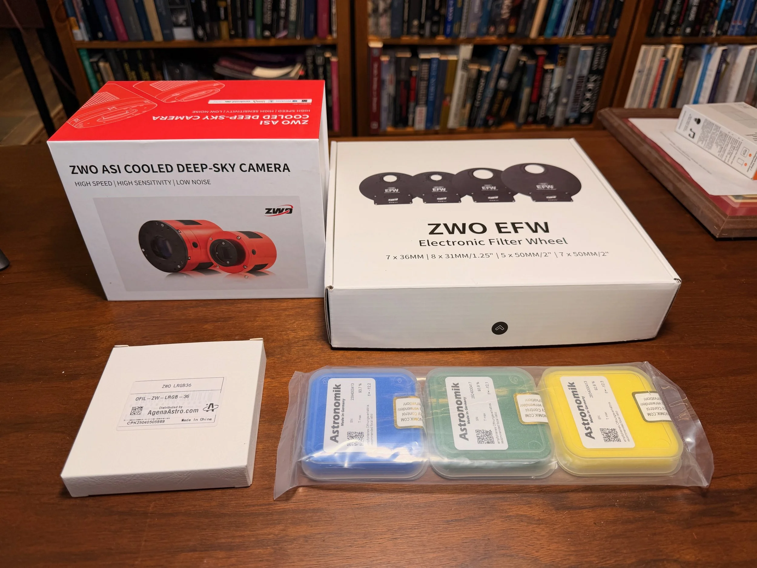
The components to the new camera stack ready for assembly!
Filter Wheel
With the larger sensor size, I could no longer use my old filter wheel, and that had to be upgraded as well. I used the ZWO EFW 7x36mm on my other platforms, so I ordered the same unit for this upgrade.
I was surprised to see that some changes had been made to this model. The first thing I noticed is that the USB connector is USB-C, and they moved it from the outer flat edge to the middle of the body.
I was really happy to see this:
I think the USB-C connector is much more robust and easier to plug in
The new location would make it much easier to avoid cable entanglements when using the camera rotator.
The next thing I noticed was that there were built-in rubber gaskets around each screw in interface on the EFW and tape plugs over all of the mount holes. In the past, I had to use black tape to seal these areas and prevent light leaks. This is a good practical improvement.
I want to mount the filters as close to the camera sensor as possible to avoid vignetting, and my practice has been to remove the tilt sensor from the camera and bolt the unit directly to it. It also provides a really solid connection between the camera and the EFW.
What Changes? What Doesn’t?
The larger APS-C sensor will cover a slightly greater field of view: about 32% more width and 17% more height.
With the previous camera, the whole system was slightly undersampled. That part has not changed. While the sensor is larger, the pixel sizes are almost exactly the same, so there is no improvement in sampling. For most wide-field views, this is no big deal. For those where it is of concern, I apply a 2X Drizzle Processing.
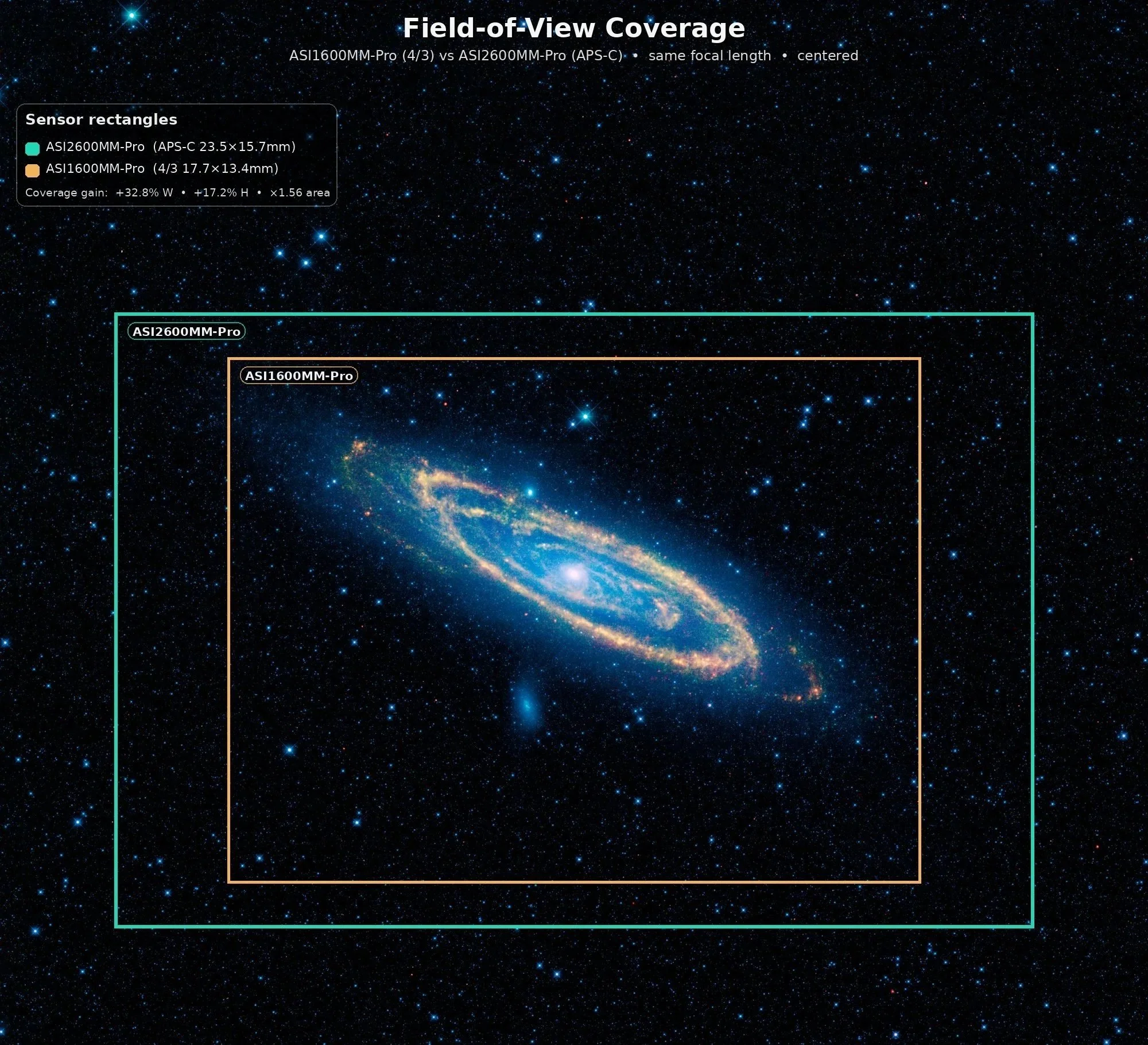
The APS-C format sensor allow a greater field of view o be captured.
A Motorized Cap with a Flat Light Source
I have been trying to move things towards greater automation. Right now, I have to go up to the observatory to open the roof and remove the lens caps from the scopes.
I also have to go to close the roof and put the lens caps back on.
I also have to spend time in the observatory to get my flat exposures. This is because I need to move my flat panels between scopes, then cap the scope for the dark calibration frames.
I have been thinking that a motorized cap would help here:
It would allow me to create flats while working from my Astro Man Cave. I could just turn on the light source and shoot my flats. Then I could turn off my light source and do my darks. When done, the scope could be covered. Shooting flats for up to 7 filters for four scopes can take a while. Automating this would be a huge convenience.
I could remotely open and close the scope as needed. Sometimes during the year, I can leave the scope open for a long while waiting for the darkness or to cool things off. But during pollen season, it’s nice to have the scope uncapped only when you need it uncapped
The unit I was interested in is the Wanderer Astro Motorized Cap V4-EC. These appeared to be well-engineered, and I found the prices reasonable compared to some other offerings.
They come in various sizes, and you choose the size not by the diameter of your telescope, but by the diameter of the dew shield it will mount on.
The dew shield for the FRA400 measures in at 100mm. I could have ordered the 100mm size, but I wanted to ensure the flat-field illuminator fully covered the dew-shield area, so I opted for the 125mm size.
Another thing I like is the built-in dew heater. When open, the flat panel can cool off, and dew can form on it. The dew heater has three different power levels. The lowest level will keep dew from forming, while higher power levels will dry things if needed before closing the cap.
I decided to try one of these units out on the FRA400. If I am happy with how it works, I will get one for the other scope platforms as well.
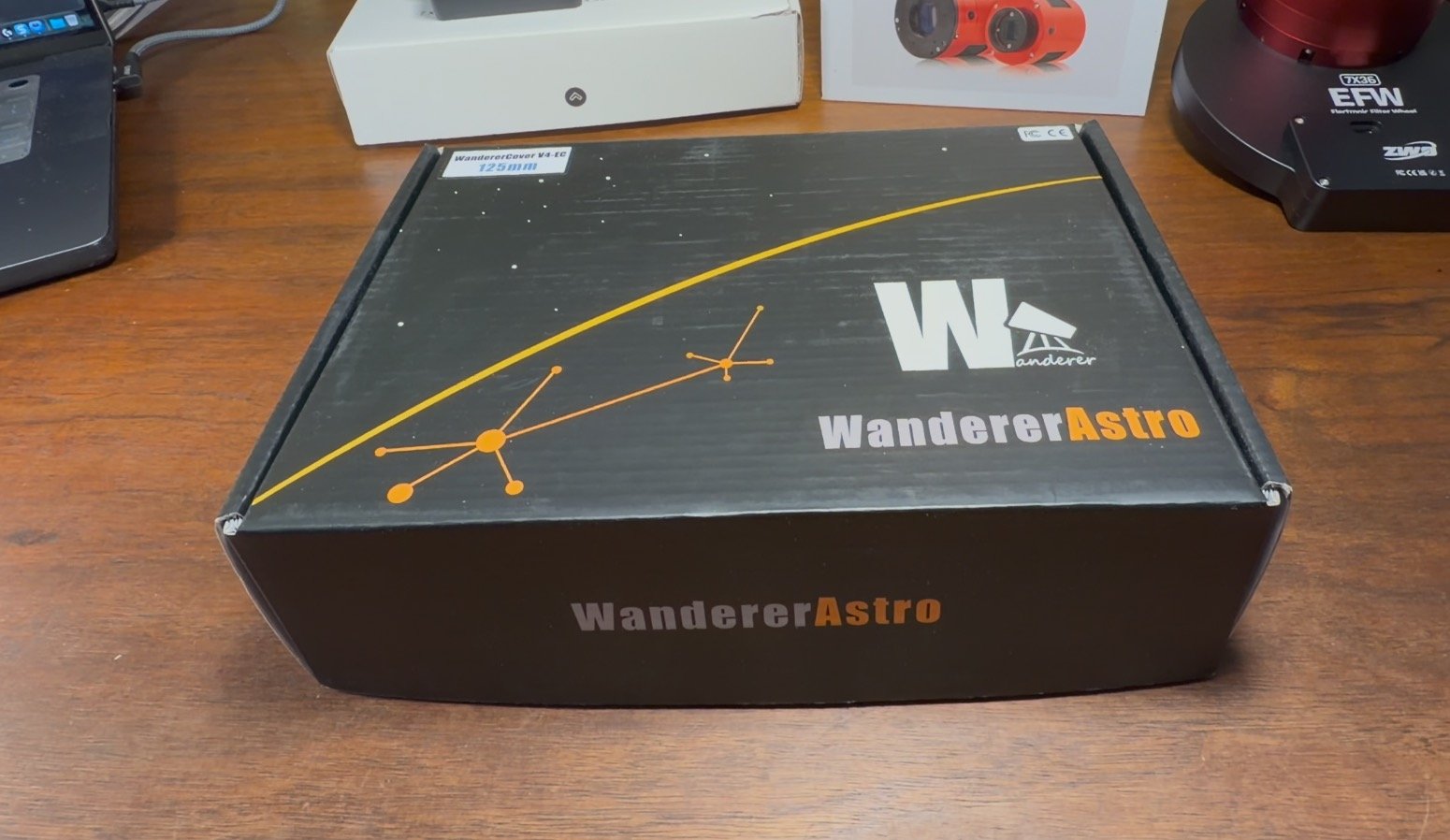
The Wanderer Astro WanderCover.
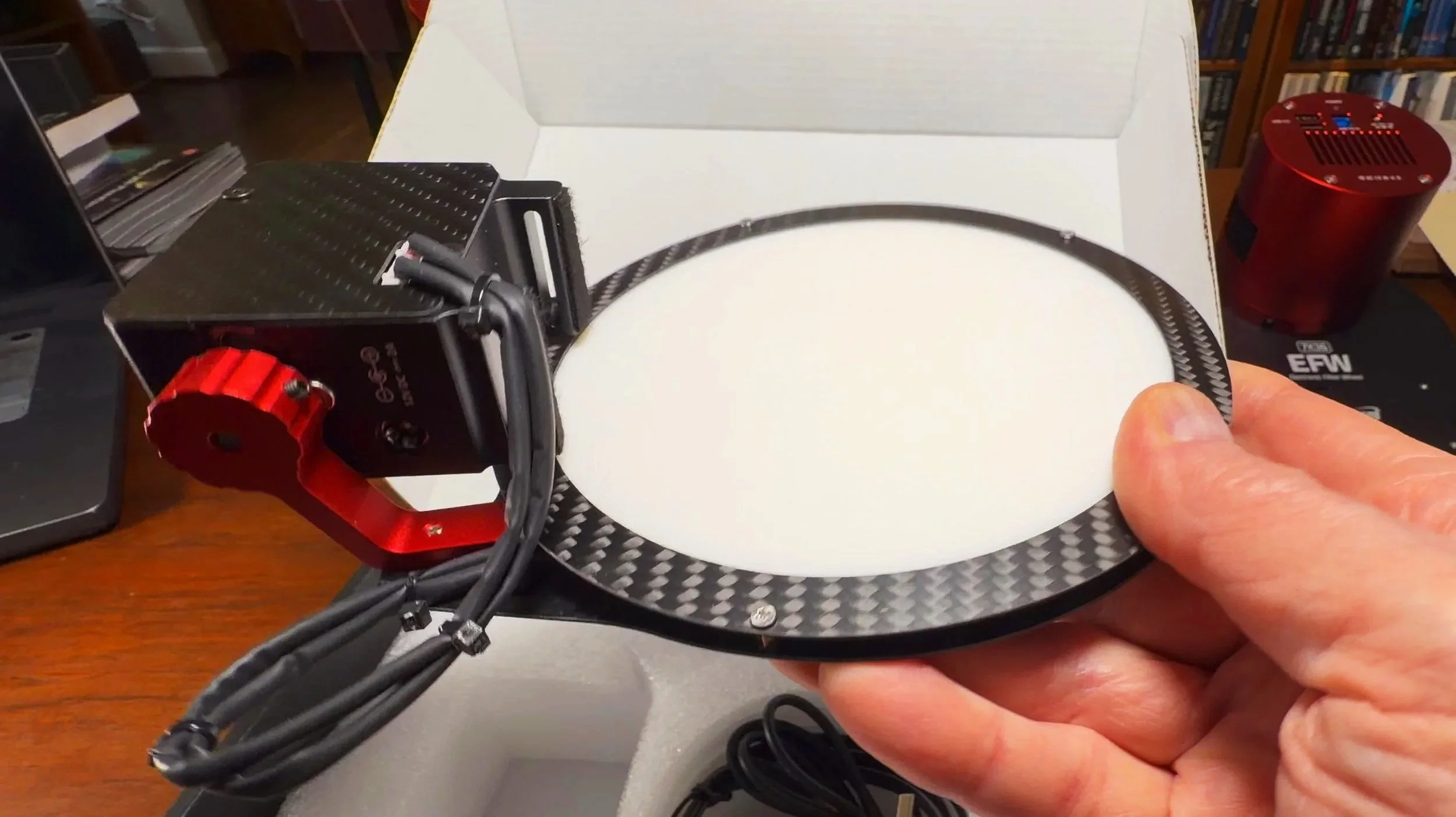
Here is the main unit.
Assembling the Camera Stack
This will be the fourth ASI2600MM-Pro/EFW 7x36mm combination that I have set up, so this is not my first rodeo.
Getting the unmounted filters secured in the filter wheel is tricky and nerve-racking, but I know how to do it.
I thought the tricky part would be doing this in a way that would maintain my current focus point. The camera and filter wheel are both physically larger, and I was sure I would have to get creative to achieve the right spacing.
But as it turns out, this was easy!
The goal is to keep the sensor at the same distance from both cameras.
The ASI1600MMM-Pro has its sensor 10.5mm from the front of the camera. There is a 1mm connector ring, followed by a 20mm-wide filter wheel. So the whole stack is 31.5mm.
If I set up the ASI2600MM-Pro the same way, I would have 17.5mm from the sensor to the front of the camera, a 1mm adapter ring, and then 20mm of filter wheel, giving me a stack of 38.5mm.
But what I like to do is bolt the filter wheel directly to the camera. To do this, I must remove the tilt plate from the camera. This changes the distance between the sensor and the front of the camera to… 10.5mm - the same as the 1600 camera!
So now my stack is 10.5+20= 30.5mm. Add a 1mm spacer ring, and I should be almost exactly where I was before!
It’s true that I will no longer have a tilt adapter, but I have never needed it on my previous three scopes, so I am hoping this will be the case here.
Mounting the EFW to the Camera
So my first task is to remove the cover plate from the EFW and then remove the wheel itself.
Getting ready to remove the top plate. Note the rubber gasket that is now built-in! (click to enlarge)
With the cover off, we can see the internal mechanism. In order to mount the EFW to the camera, we must also remove the filter wheel. This is not a bad thing as installing the filters is easier with the wheel out. (click to enlarge)
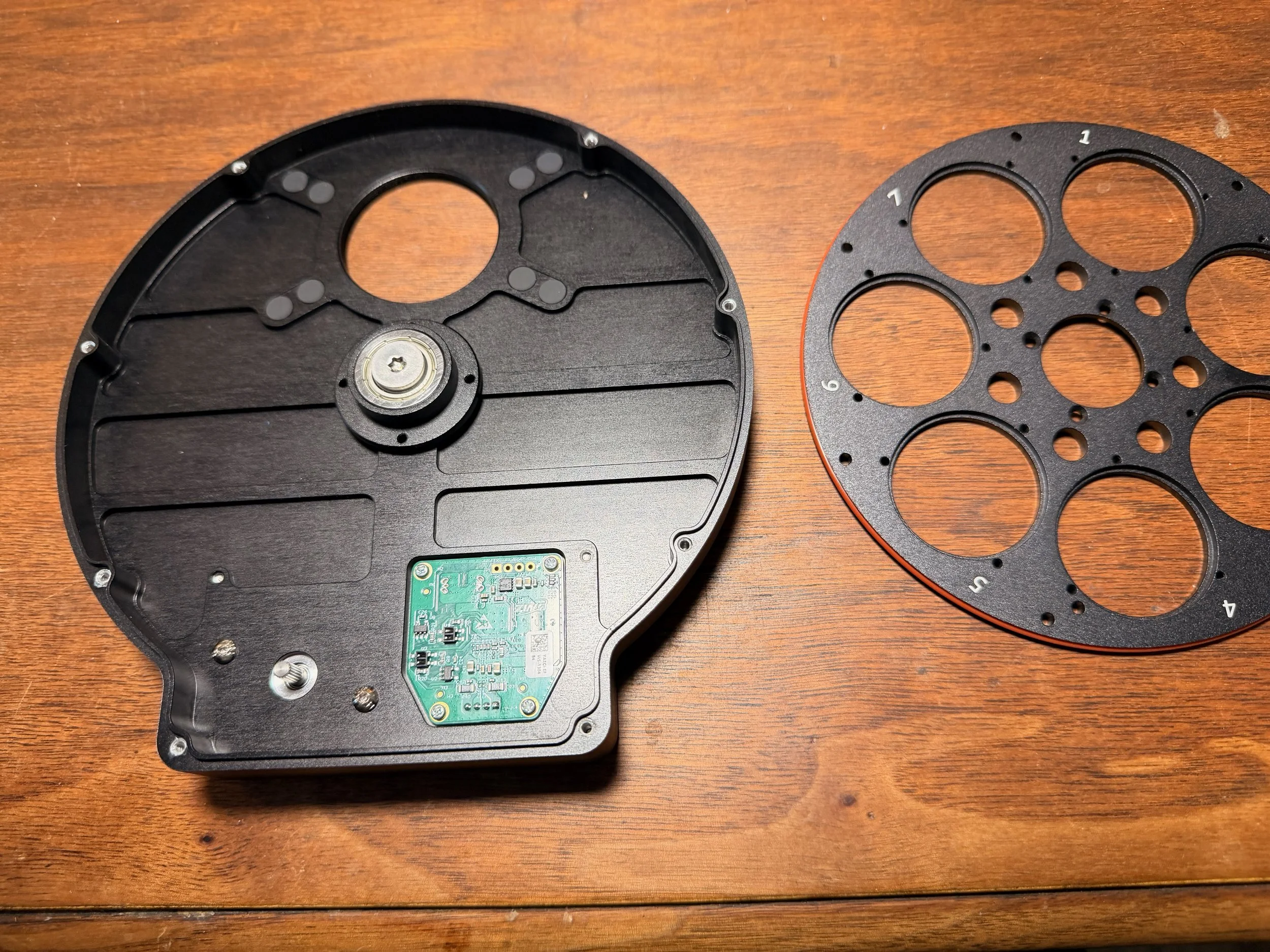
The four screws holding the wheel in are removed and we can now see the two sets of four mounting holes. These are covered by light-blocking plugs.
Then I remove the tilt adapter from the camera.
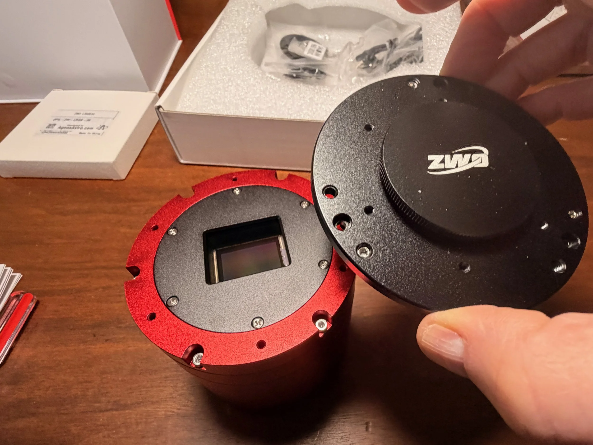
Removing the tilt plate also removed 7mm of space between the sensor and the filter wheel. This is a good thing!
With the filter wheel out of the way, I can mount the EFW directly to the camera with 4 screws. Note the rubber gaskets and the plugs over the unused screw holes.
A close up on the mount hole, plugs still in place (click to enlarge)
The outer set of holes are needed for bolting to the camera. I removed the plugs and now you can see 3 screws mounting the EFW and so you can see the filter aperture. (click to enlarge)
Mounting the Filters
This is a tricky operation.
You don’t want fingerprints or dust on the filters or in the EFW, so work in a clean area and wear gloves. Even then, you will encounter dust, so keep an air bulb nearby to remove specs as you see them.
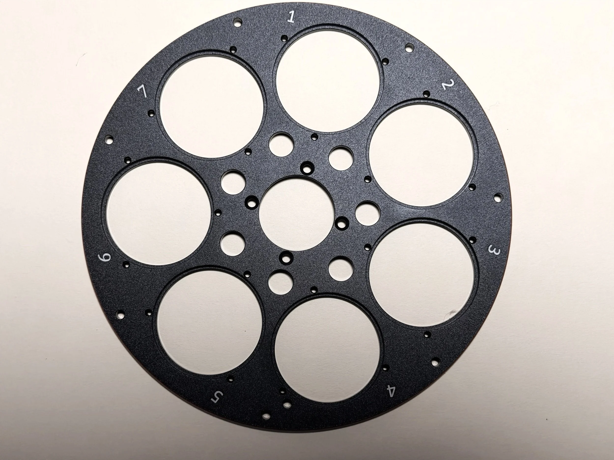
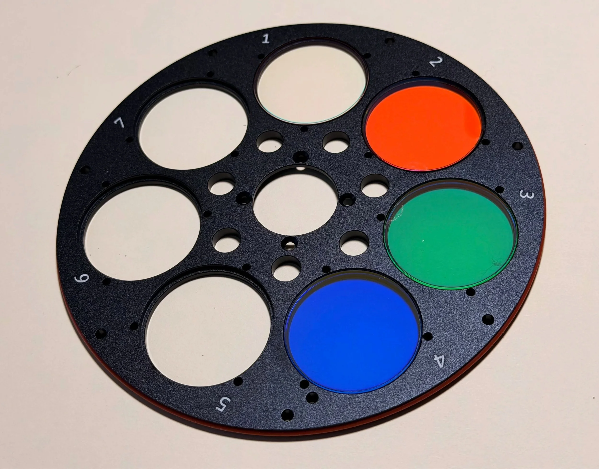
The filter wheel. We will start with slot #1 and place the LRGB filters in the first four positions.
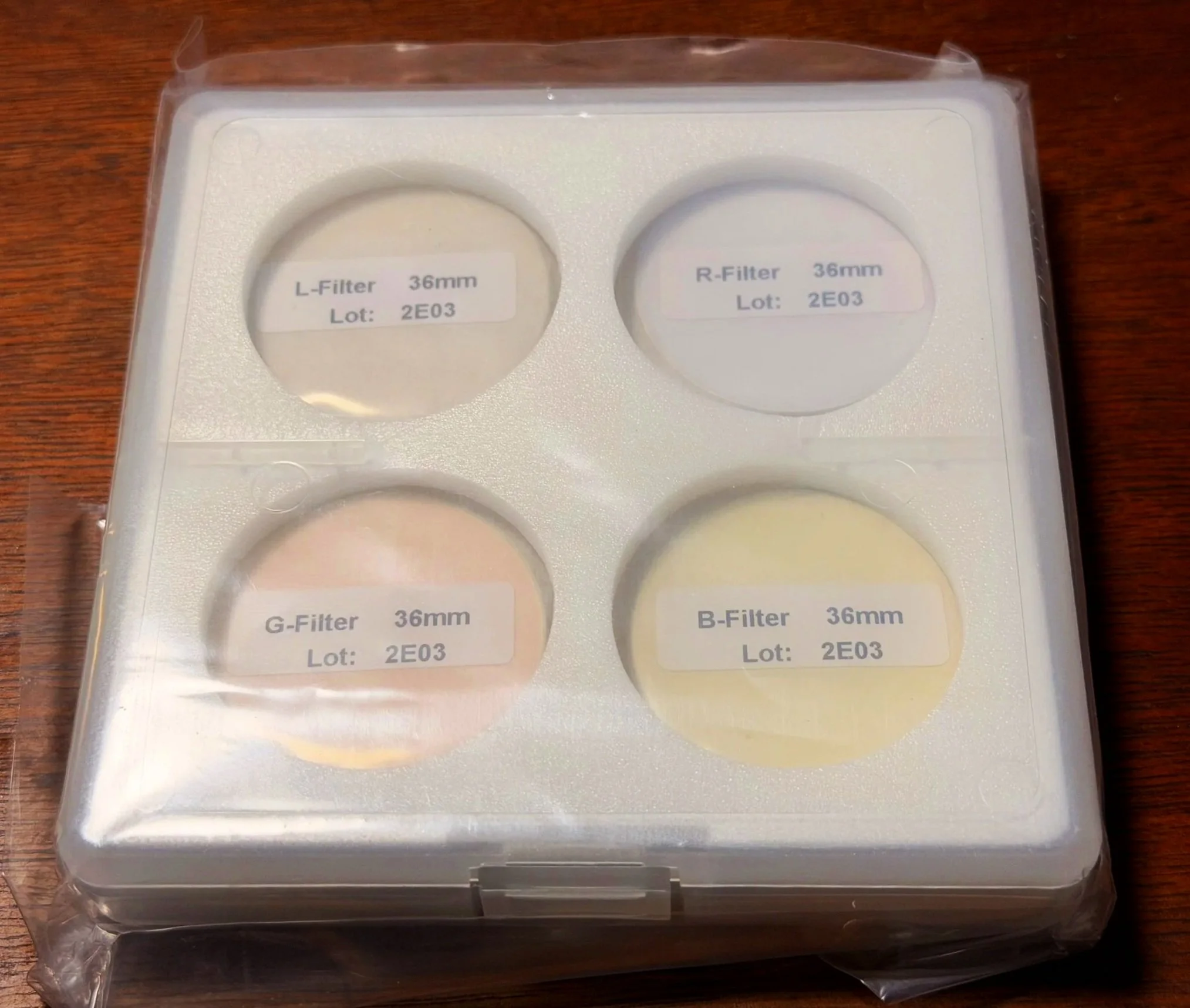
He is the ZWO LRGB filter set before installation..
Now the LRGB fillters are in place. Slot #1 looks empty but it does have the L filter in place.
First, I deal with the LRGB broadband filters.
I bought a set of ZWO 36mm unmounted filters. I have had good results from these in the past, and they are cost-effective, so I am using them again.
You need to carefully remove them from the plastic envelopes and the lens wrap they are packaged with. I use sharp scissors to cut off one side of the filter package and carefully extract the filter. Place each one in a cell on the filter wheel - L in slot #1, R in slot #2, and so on.
For the narrowband filters, I used Astronomik 6nm cut filters. Again, I have used these, and they are excellent for the price. These are thicker filters because of the metal mount band around them. This makes them easier to handle safely, but the thickness adds a challenge when installing the filter retainer rings. While they are thicker, they are not too thick for the EFW to handle.
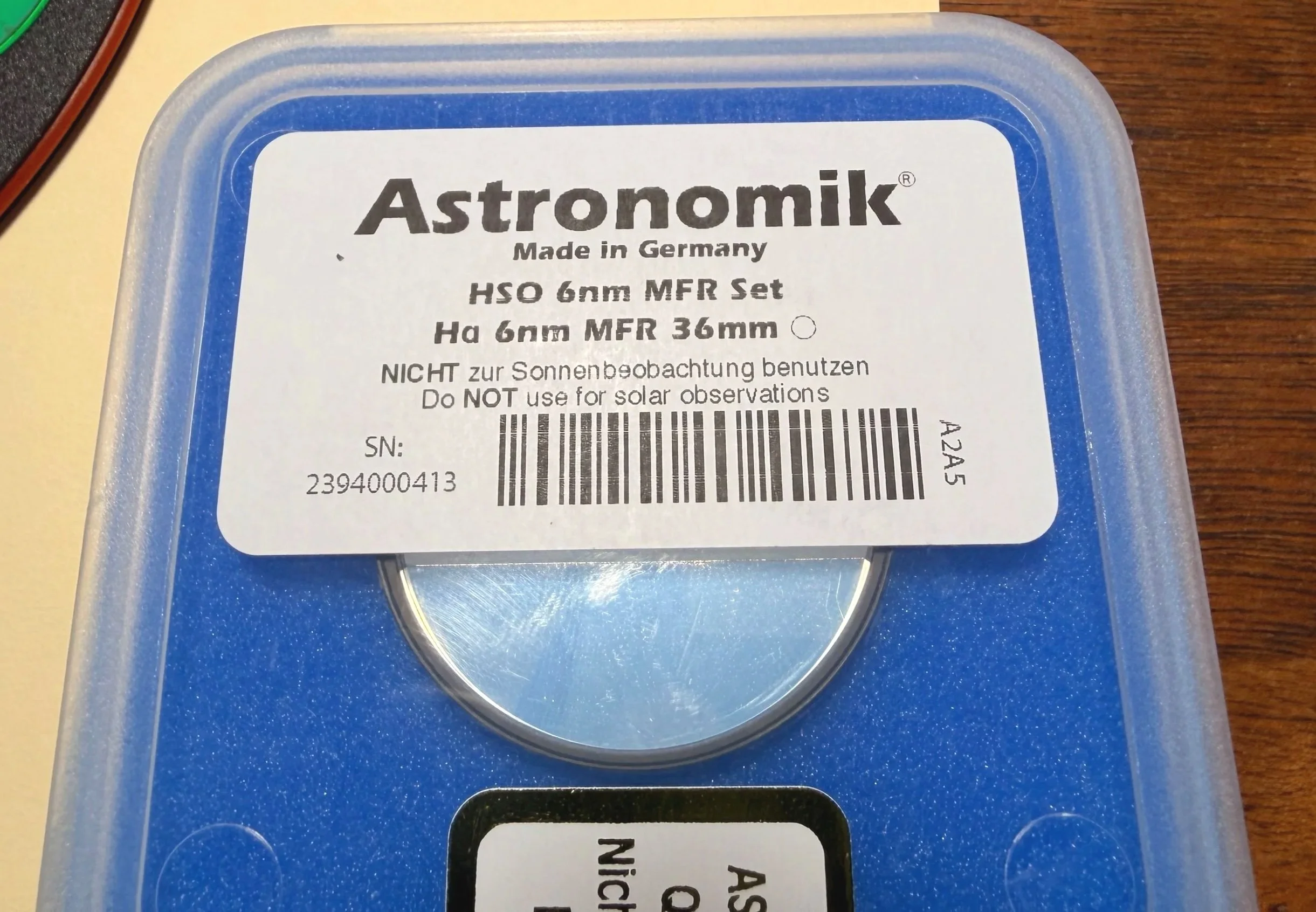
The Ha 6nm cut filter.
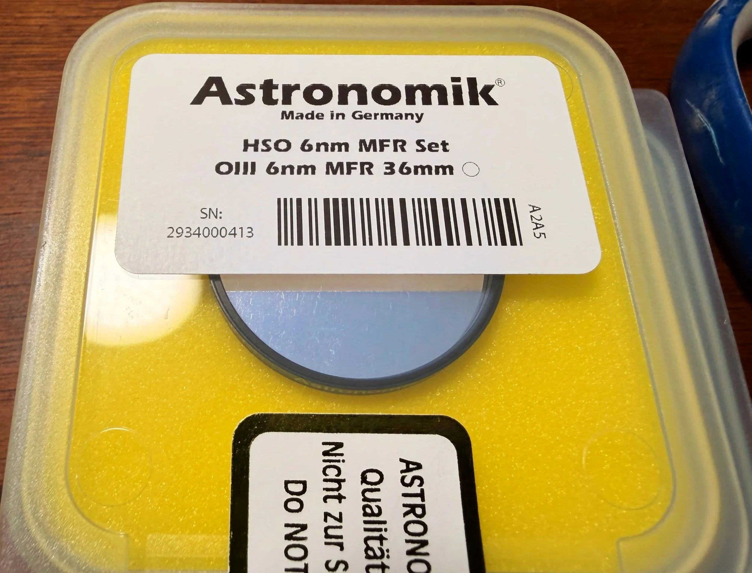
The OIII 6nm cut filter.
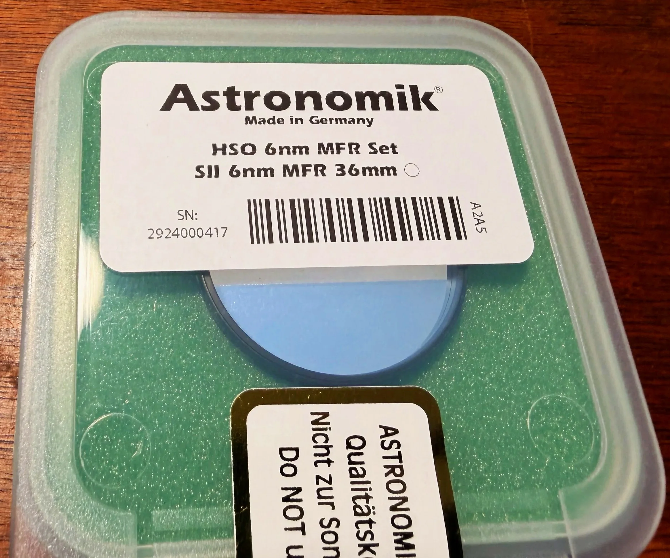
The SII 6nm cut filter.
Note: both filter sets are coated on both sides, so which side of the filter goes where is no longer a concern. It used to be that ZWO filters had anti-reflection coatings on only one side, and it was tricky to get this right. But now that is no longer the case, so you don’t have to worry about it.
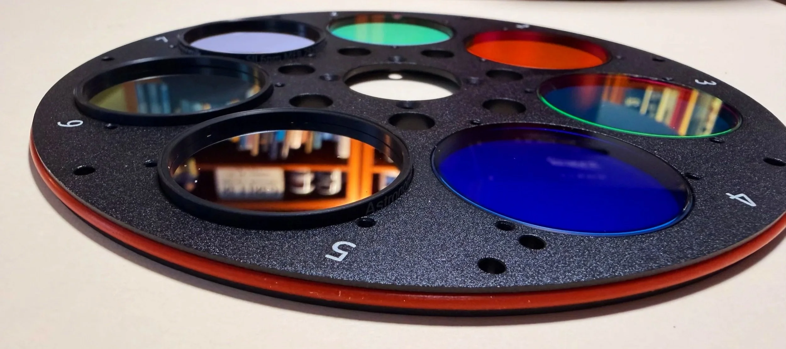
The filters all in place. This close up shows the difference in thickness between the narrowband and broadband filters.
Once the filters are in place, it is time to install the circular filter retainers.
These retainers have a dull side and a shiny side; put the dull side up. Sometimes this difference between the two sides is minimal. In other cases, it is more obvious.
Three tiny screws hold them in place. I use a very thin needle-nose pair of pliers to hold the screw in place and get things started. It would be very easy to slip and scratch a filter, so slow and easy wins the race here.
The ZWO filters are relatively easy to use. The Astronomik has a thicker cell, which makes it harder to install, but if you are careful, you can get it done easily.
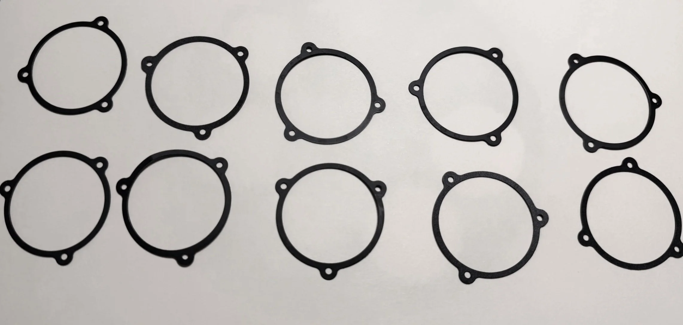
The filter retention rings.
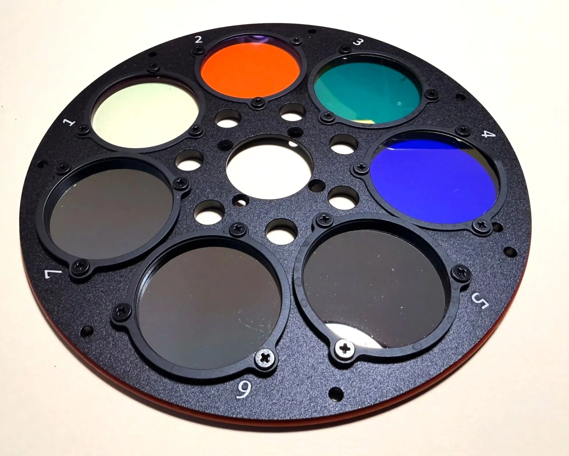
The filter retention rings are now all installed. Make sure to blow dust off of the filters - despite your best efforts, you will have some!
Then reinstall the wheel.
Make sure that the filter holders and cell numbers are facing up. It is possible to install the wheel backwards and then all kinds of crazy things can happen. (Take it from a guy whose been there, done that, and got the T-shirt!).
Check for any dust that needs to be removed, then put the cover plate back on.
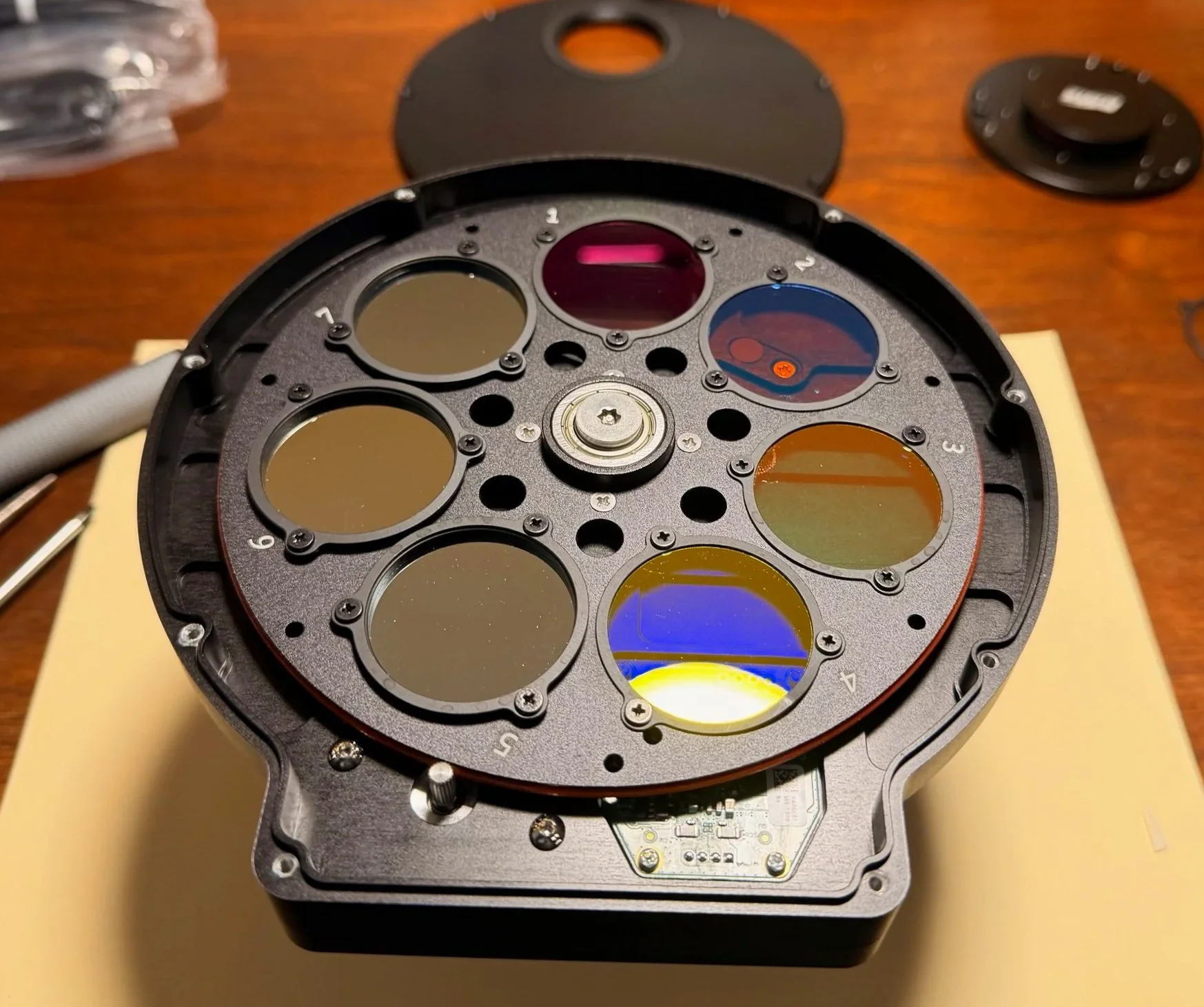
The filter wheel now installed back in the case.
The camera stack is now done and is ready to be added to the telescope stack right at the filter wheel interface!
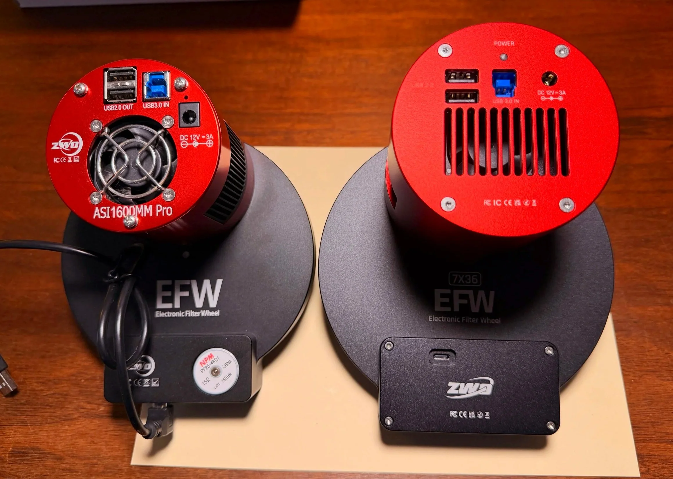
The new camera is much larger than the old one! Note the USB—C plug on the new EFW. Moving this from the outer edge to here will solve the problem of cable snags between the EFW and my Falcon Camera Rotator!
Installing the Camera
Installing the new camera stack was super easy. I just unplugged the cables and unscrewed the old camera stack at the back of the filter wheel. Then I screwed the new camera stack back in place at the same spot with the 1mm spacer ring, plugged in the cables, and I was done!
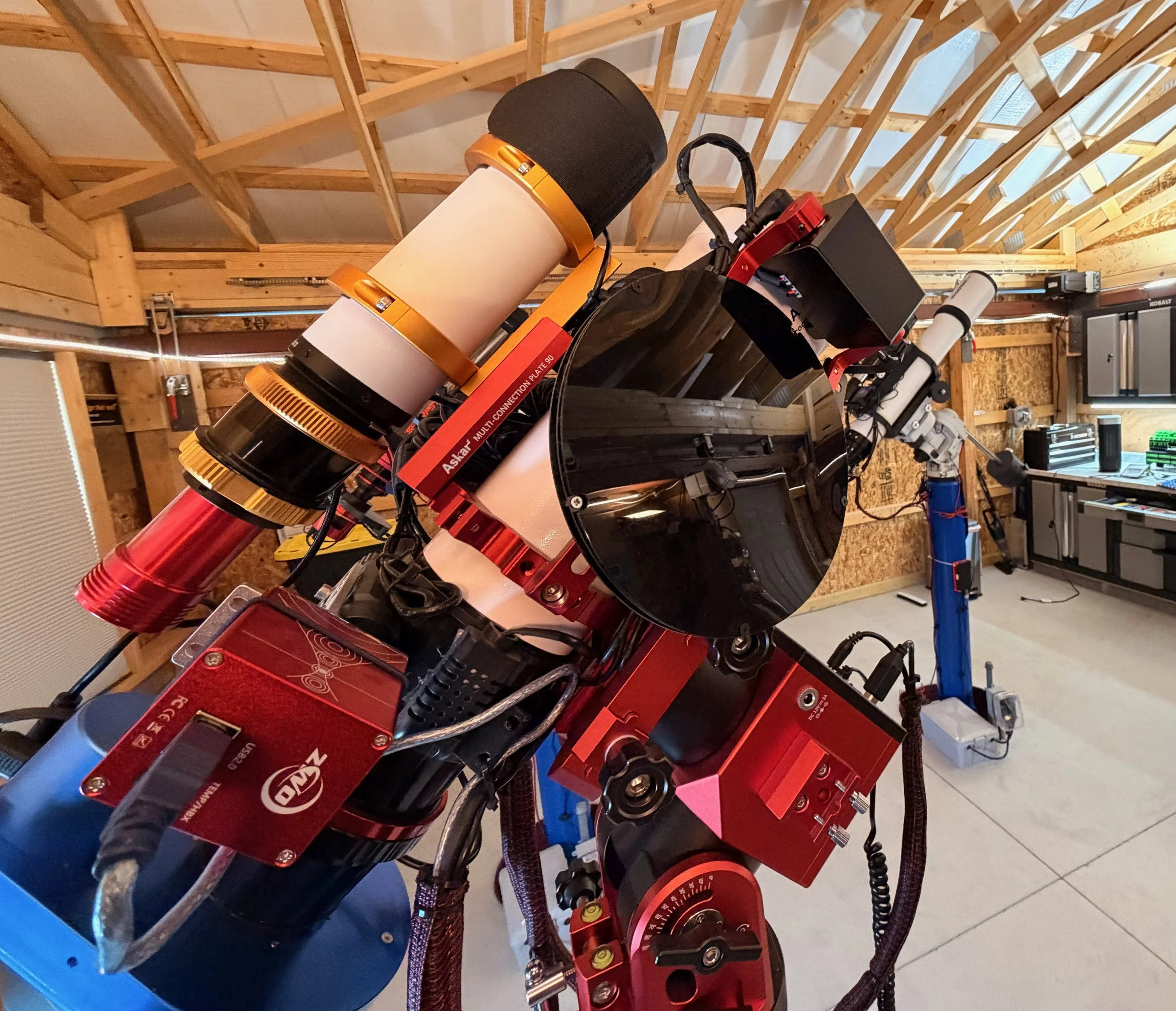
The camera installed and ready to go. (click to enlarge)
The view form the other side (click to enlarge)
Installing the Motorized Cap
In general, the WandererCover is an easy install. Two fat zip-ties secure it to the dew shield, and then you plug in your power and USB connections.
But it was a little trickier for me:
The dew shield on the FRA400 is a slight friction fit. With very little effort, you can pull the shield in or out or rotate it to a different position. Not exactly the firm mounting point I wanted for the cover!
The FRA400 is a small scope, and it was not obvious how the cover should be positioned. It needed to open the cover without colliding with other components on the platform.
The dew shield of the FRA400 - I put a white tie cable tie right behind to keep the shield deployed. (click to enlarge)
After applying some packing tape to prevent rotation of the shield, the dew strip is back in place and we are ready to proceed with mounting the cover. (click to enlarge)
To test different mounting positions, I mounted it using some large tie-wraps I already had. These would be sacrificed to test fit. Having done this, I found that the best position had it mounted so that it opened to the side of the scope and could open up to 270 degrees before it hit anything.
I then moved the scope through its different positions to ensure that the open cover would not snag on something.
With this behind me, I mounted the cover on the dew shield and cut the excess cable tie ends.
The cap in the process of opening. (click to enlarge)
The Cap in the fully open position. (click to enlarge)
At this point, I was ready to work with cables, so I installed the software and hooked everything up.
WandererEmpire is the main driver software for all Wanderer Products and has a pretty intuitive interface. You can use this to connect to the cover and control it.
This also sets up ASCOM drivers, allowing it to work with NINA and ASIAIR control interfaces.
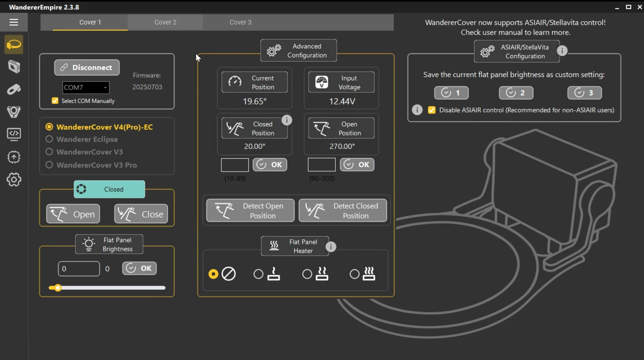
The control screen for WandererEmpire.
In NINA, you can connect to the device; if WandererEmpire is not running, it will launch and allow you to connect. Once connected, you get access to the critical operational functions.
FlatWizard can use it, and you can also control the cap in a sequence using the Plugin.
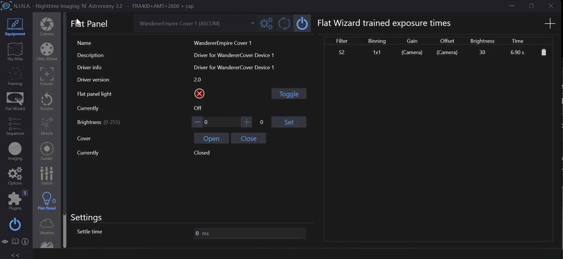
Connecting the Flat Device in NINA exposes the controls available for use from within that environment.
I had an available 12v supply feed and a slot on my USB hub, so that was simple. I just let the cables dangle while I tested the functionality. When I was happy with that, I did some cable management.
WandererCover ND Filter
Subsequent testing suggested that the lowest brightness level was still too bright for this fast f/5.6 system. Fortunately, I had ordered the optional ND filter for the 125mm cover. This costs about $7 at Agena Astro and indicates that it increases exposure times by 32X. This would be a 5-stop decrease in light and an optical density of 1.50.
The ND filter is a solid piece of plastic with protective films on both sides that needs to be removed.
The filter then has a set of large notches and small holes. The idea is to leave the screws in the cover alone in those locations where you see the large notches. Remove the screws where the small holes are located. If you remove all the screws, the LED panel will fall out, and you don’t want that!
The ND filter comes with small black screws with larger heads for mounting the filter. The trouble I had was that the Allen head on the screws was smaller than any metric Allen wrench set I had. My smallest was 1.5mm, and this was still too big for these screws.
Then I remembered that I had a small powered screwdriver built for use on small electronics. That set had bits down to 0.7mm, and I found that the 1.3mm Allen head fit perfectly. So much so that I could mount the screw in the bit, and it would stay there as I went to thread it in.
I added this onto the face of the flat field illuminator, and this brought flat exposure times down where I wanted them.
The ND Filter kit for the 125mm size. (click to enlarge)
Comparing the ND filter to the face of the cap. Note the holes vs. the notches. (click to enlarge)
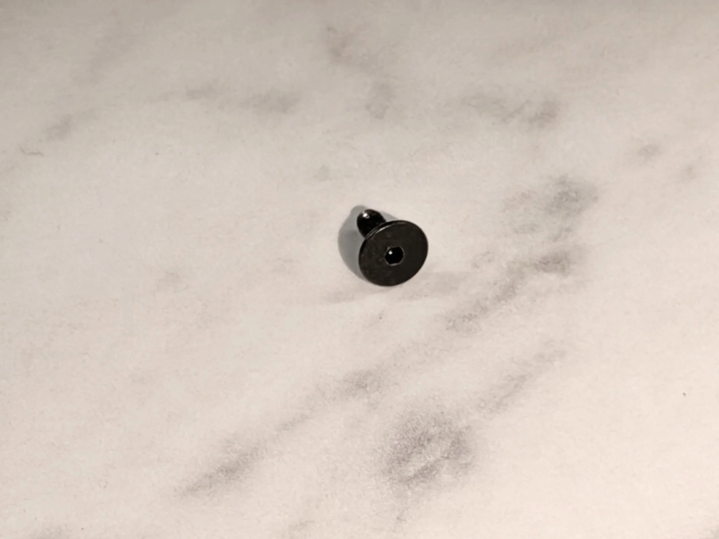
This is a close up the new replacement screws used by the ND filter.
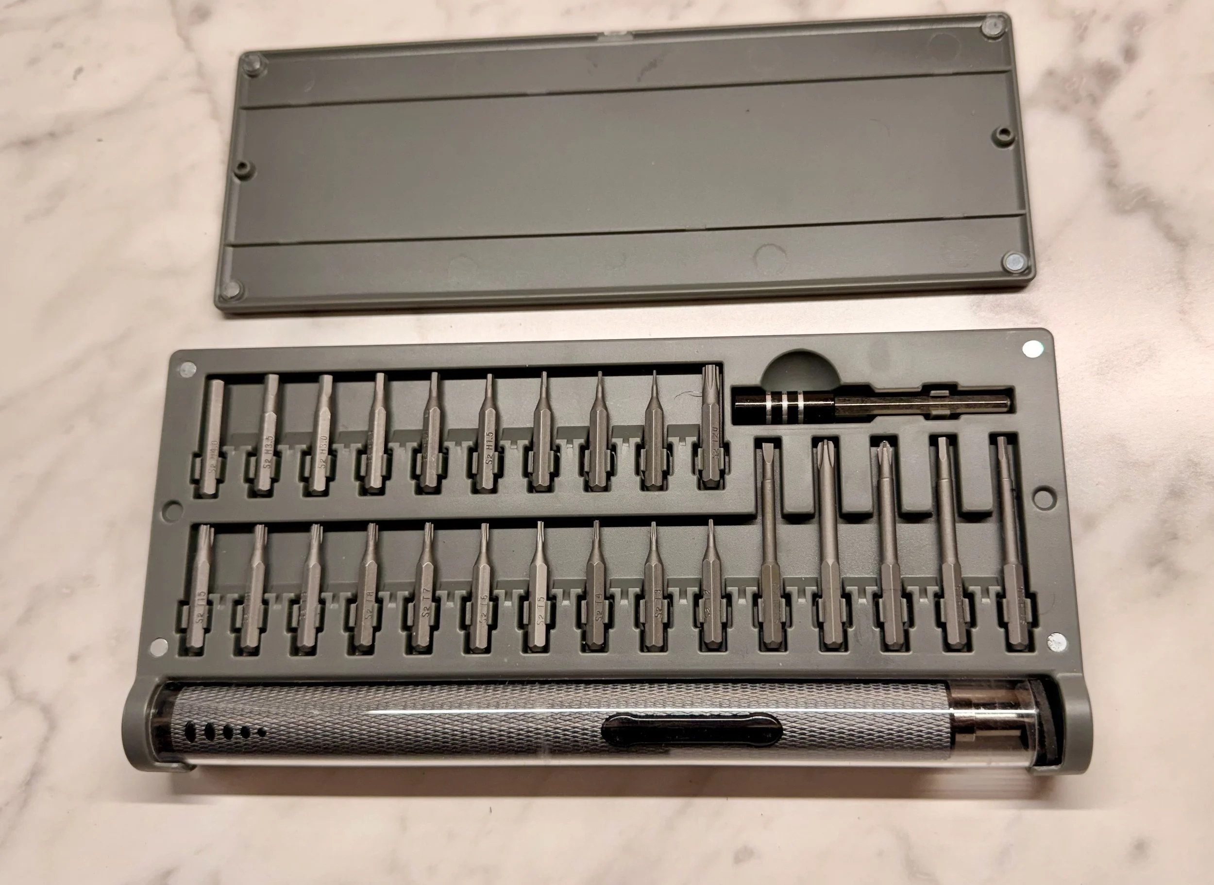
This small-electronics kit powered screw drive had the small Allen bit that I needed - 1.3mm.
The ND filter now in place.
Conclusion
As I am writing this, I have not yet had a chance to shoot any targets with this setup. Once the depressing winter cloud deck finally breaks, I will add images shot with this new platform configuration here for reference.
I am really looking forward to using this new version!
The Final Version 3.0 Configuration:
Scope: Askar FRA400 72mm f/5.6 Quintuplet Air-Spaced Astrograph
Focus Motor: ZWO EAF 5V
Guide Scope: William Optics 50mm guide scope
Guide Scope Rings: William Optics 50mm slide-base Clamping Ring Set
Mount: ZWO AM5
Mount Base: Custom Steel Pier
Camera: ZWO ASI2600MM-Pro - New
Camera Rotator: Pegasus Astro Falcon Camera Rotator
Filter Wheel: ZWO EFW 7x36mm - New
Filters: ZWO 36mm unmounted: LRGB Gen II, Astronomik 6nm Ha, OIII, SII - New
Guide Camera: ZWO ASI290MM-Mini
Dew Strips: Dew-Not Heater strips for Main and Guide Scopes
Power/USB Dist: Pegasus Astro Powerbox Advanced
Motorized Cover: Wanderer Astro WanderCover V4-EC 125mm w/ND filter.
Computer: Mele Quieter-4C Fanless microcomputer running Windows 11