Askar FRA400 Platform Version 2.0: Changing to the ZWO AM5 Harmonic Mount!
Dates: Dec 27, 2022 - Now

The Askar FRA400 Platform now with the ZWO AM5 mount!
Table of Contents Show (Click on lines to navigate)
Platform Change Summary
Since I first put the FRA400 platform together, I have used the IOptron CEM 26 as my Mount. I have recently decided to change over to the new ZWO AM5 Harmonic mount.
There are many reasons for making this change, and I will be covering them here in some detail.
There have been some issues on the CEM 26 that have pushed me away from that mount.
There have also been some things that have pulled me toward the AM5 mount.
Let’s talk about my experience with the CEM 26 Mount first.
Video Discussion
Below is the companion video from my YouTube channel for this Mount Update. Please consider Subscribing and ringing the bell to support this fledging channel!
Here is a video overview of the final configuration of the Askar FRA400 Plafrom on the AM5:
The CEM 26
I initially chose the CEM 26 because I wanted a small, light, affordable mount for portable operations. At the time, the CEM 26 was a new product offering that seemed to be based on the venerable CM25. It offered a 10 lb head that could support a 26 lb load for astrophotography.
It was certainly affordable compared to many others.
I chose this mount and the lighter weight 1.5” tripod and found this combination worked well for those times I wanted to operate away from my driveway.
It was relatively light, easy to set up, and had a built-in iPolar camera for quick Polar Alignment. It was also very quiet when working - fast slews were smooth, and you could barely hear the motors running.
I used this configuration for over a year and have gotten some really nice images with it.

The CEM 26 Mount.

My FRA400 Platform on the CEM 26 mount.
But it had its issues.
DEC Backlash
The first issue I ran into was backlash on the DEC axis. I found I had over 5 seconds of backlash when I first received the mount, so I contacted IOptron support, and they quickly provided me with a one-page procedure for adjusting the tension of the DEC drive belt. Increasing the tension reduced the backlash from 5 seconds to under 1 second. The residual backlash was easily handled by the PHD2’s backlash compensation mechanism and the right DEC guiding parameters.
At this point, I was happy with the solution - if it stayed constant.
But it was not constant.
I found that over time, the belt tension would change, and my DEC backlash would begin to grow again. This meant the backlash on the DEC axis was constantly changing - not a good thing. It also meant that I had to keep adjusting the tension. Not a convenient thing.
Adjusting the tension meant that I had to remove the outer drive housing, loosen the screws that mounted the belt drive motor, and then use a screwdriver to leverage the motor such that more tension was placed on the mount. Then I could tighten the screws holding the motor.
So if things are drifting - then just tighten the motor mount screw more so that they don’t move with time - right?
Well - not really.
It turns out that one part of the mount was plastic - and I was afraid to crank down too tightly on the mount for fear of cracking the plastic. I really wish that IOptron had made both parts of metal, and then maybe I could control this issue.
So dealing with an ever-changing level of DEC backlash was frustrating.

Looking at the housing I must remove to adjust belt tension on the DEC axis.
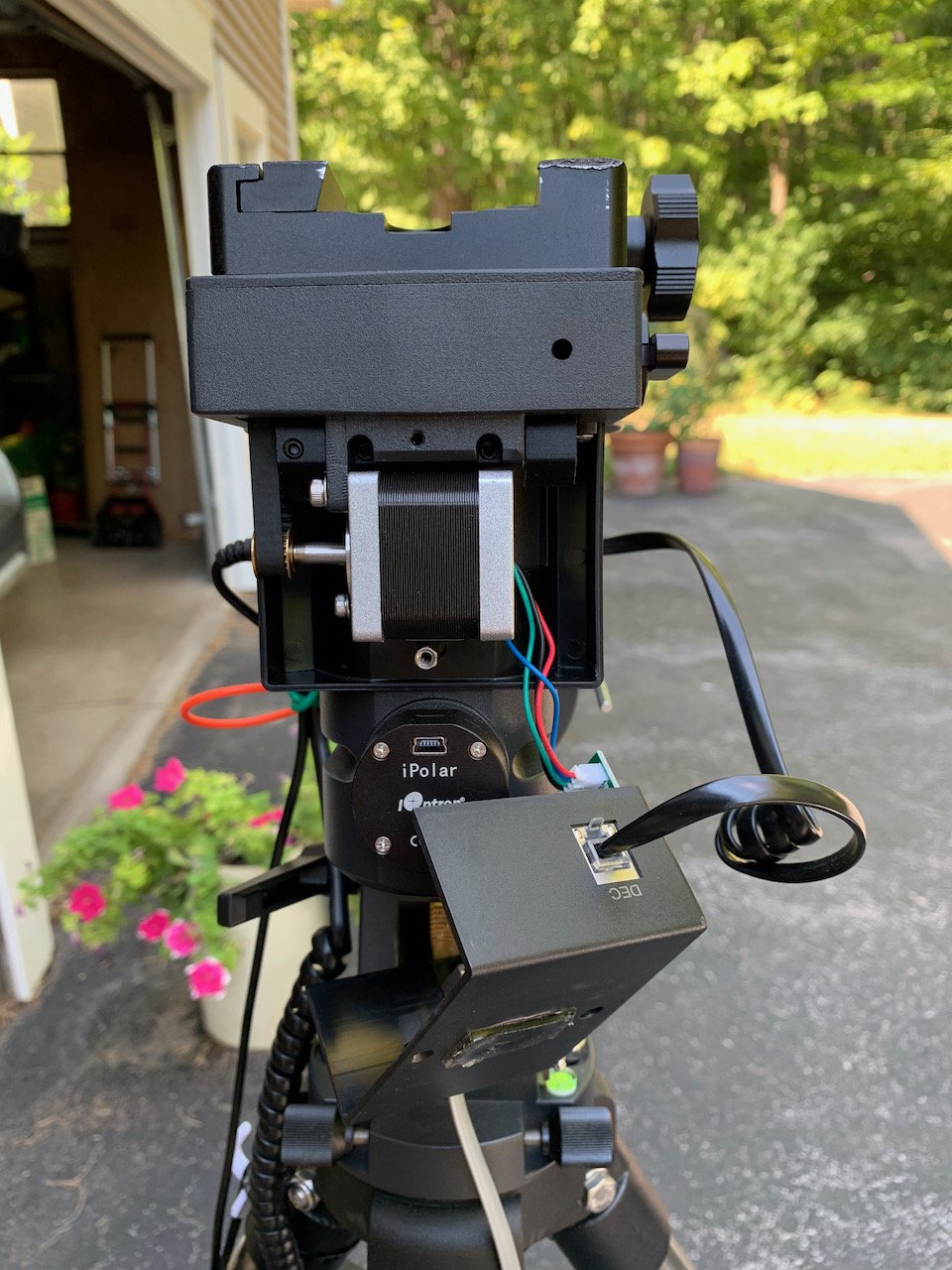
The cover is now removed and you can see the drive motor.

Looking from the side, you can see the belt whose tension needs adjustment.

On the upper right, I screwdriver is used to leverage the motor to put more tension on the belt. The Allen wrench on the left is tightening the motor in this new position.
Balancing

Here filter wheel is moved off-center by the rotator. Rotating the Filter wheel can impact the balance.
The CEM 26 is a fairly typical equatorial drive. It has a larger RA gear and a small worm gear to drive it. It would work quite well if you took the time to ensure your load was well-balanced. In general, this was easily done. You loosen the clutches and ensured that your load was balanced in each dimension.
But I had a mono camera with an electronic filter wheel. In addition, I had a camera rotator. As the camera rotator moved the camera to get the composition I wanted, it moved the filter wheel to different locations for each shot. This change was enough to alter the balance needed - sometimes by a little, sometime by more. This would impact the guiding, and sometimes I need to touch up the balancing for each target.
This was NOT convenient.
Weight
While the head of the mount only weighed about 10 lbs, for it to work effectively, it needed a counterweight. The counterweight also weighed 10 lbs. So, in reality, I had a 20 lbs mount, carrying a 12 lb load, all mounted on an 8.4 lb steel tripod. This combination weighed in at 40.4 lbs. This was not outrageous by any means, and I routinely lifted and carried the mount from the driveway to the garage where it was stored.
But I have bad knees and an arthritic back, and even this was starting to be a bit of a chore.
RA Axis Wobble
When I first got the CEM 26 mount, I could lock the clutches, and the RA axis would be rock solid. But with time, some wiggle began to develop with the RA axis. This was a problem. I also started to get some elongated stars on my tracking. Clearly, something inside the mount had loosened up and allowed some slop into the system.
I guess that this is something that can be corrected - but it was another Issue.
Pushing Me Away From the CEM 26
These, then, were the factors that were pushing me away from the CEM 26 mount and making me consider what my alternatives might be. It could be that all of these factors could be addressed - but the fact they existed at all made me start thinking.
While I say that some of these issues pushed me away from the CEM 26, I should note that I am far from done with this mount. I plan on working on it this winter and seeing if I can resolve the issues I have been seeing. I may have a fourth Scope platform on the driveway starting next year!
The ZWO AM5 Mount
As I considered alternatives, I started hearing more and more about the ZWO AM5. it was billed as a super lightweight mount that could easily handle serious loads without needing counterweights and balancing!
It did this through the use of Harmonic Strain Wave gearing systems.
ZWO is not the only outfit that was offering a new mount based on this technology. IOptron, Pegasus Astro, and RST either had similar mounts or were working on one.
It sounded almost too good to be true. So before we talk about the specifics of the AM5, perhaps we should explore what this new gear technology is all about.

AM5 Product photo from ZWO.

AM5 product photos from ZWO.
Strain Wave Gear Systems
Harmonic or strain wave drive systems are not new. They were first described in a 1957 patent by C.W. Musser. Over the years, it has found significant use in robotics and the aerospace industry.
The strain wave design is based on the elasticity of metal. It uses three basic components:
a central elliptical wave generator (in green below)
an outer circular spline that is fixed ( in blue below)
a flex spline is positioned between the two other components ( in red below)
As the elliptical wave generator rotates, it forces the flex spline against the outer circular spline and causes the teeth to mesh at that point. As the wave generator rotates, this area of contact shifts - and since the flex spline has fewer teeth than the outer circular spline, this induces a rotation. The difference in the number of teeth drives the gearing ratio needed.

GIF animation from Wikipedia article on Strain Wave Gearing.
This style of gearing has many advantages:
Robust: Fewer moving parts
High Torgue: 30% of the teeth are engaged at any point rather than just a few gear tooth face, as is common with normal gearing systems
Smaller: The Wave Strain system can produce more torque at a smaller size than traditional worm drive systems.
No Backlash: As gears are always fully meshed, no driving gear face has to reverse and encounter the other side of the gear to change directions
Quiet: smooth gear meshing means a quieter drive
The AM5 uses this style of gearing for both the RA and DEC axes.
ZWO AM5 Advantages
Using Strain Wave Technology, the AM5 seemed to offer a very nice package:
Excellent machining, fit, and finish.
The main drive body weighs only 11 lbs.
Ability to handle a 28.6. lbs load without a counterweight, 44 lbs with one
if you can get by without a counterweight, this is results in huge weight savings.
Uses a carbon fiber tripod - more weight savings of some 3.3 lbs compared to my IOptron 1.5” tripod.
My total weight with my OTA is about 28 lbs.
Does not require precise balancing - quicker setup!
This looked very appealing.
ZWO AM5 Concerns
While I was very interested in the new technology approach and the advantages that the AM5 seemed to offer, I also recognized that was some risk as well.
Before this, ZWO had never designed a telescope mount - while they may make good cameras and camera-related gear, it was not a given that this experience would translate over to the mounting world.
This was the first version of a new design - being an early adopter has its own risks.
It was clear that the mount would be well integrated into the ZWO ASIAir ecosystem - but I would be using it exclusively via the ASCOM driver interface. ASIAIR really wants to work with only ZWO products, and I was using a Pegasus Astro Camera Rotator - which could not be driven by the AISAIR. I was not all sure of how well the ASCOM driver would be supported, and I had already heard issues around significant bugs with the early versions.
The design had all of the cable interfaces located on the part of the mount that moves during slews and tracking. This - in my mind - was not a great design decision, as it could result in cable snags - and given the torque and power of the drive, I could envision potential problems with this configuration.
The nature of the drive meant that it might not be as smooth and well-behaved as what I had experienced with a worm drive mount.
The AM5 has no direct support for a Polar Alignment Camera, such as I had with the CEM 26 - I would need to find an alternative way of dealing with this.
The mount was much more expensive than the CEM26, so If I had issues, it could be a bad use of limited funds.
Some of these concerns held me back for a while. But I reached out to owners of the AM5 via Twitter and received very positive feedback from those with first-hand experience with the mount.
Based on this feedback, I decided to place my order!
ZWO AM5 Order
I ended up ordering the AM5 mount, the TC40 carbon Fiber Tripod, and finally, the 160mm Pier Extension.

The AM5 Mount

The TC 40 Carbon Fiber Tripod

The 160 mm Pier Extension
The order was placed through AgenaAstro, which I have found seems to have an excellent supply chain when ordering new and highly desired products like the AM5. About two months later, the mount shipped and I had my first experience with the AM5.
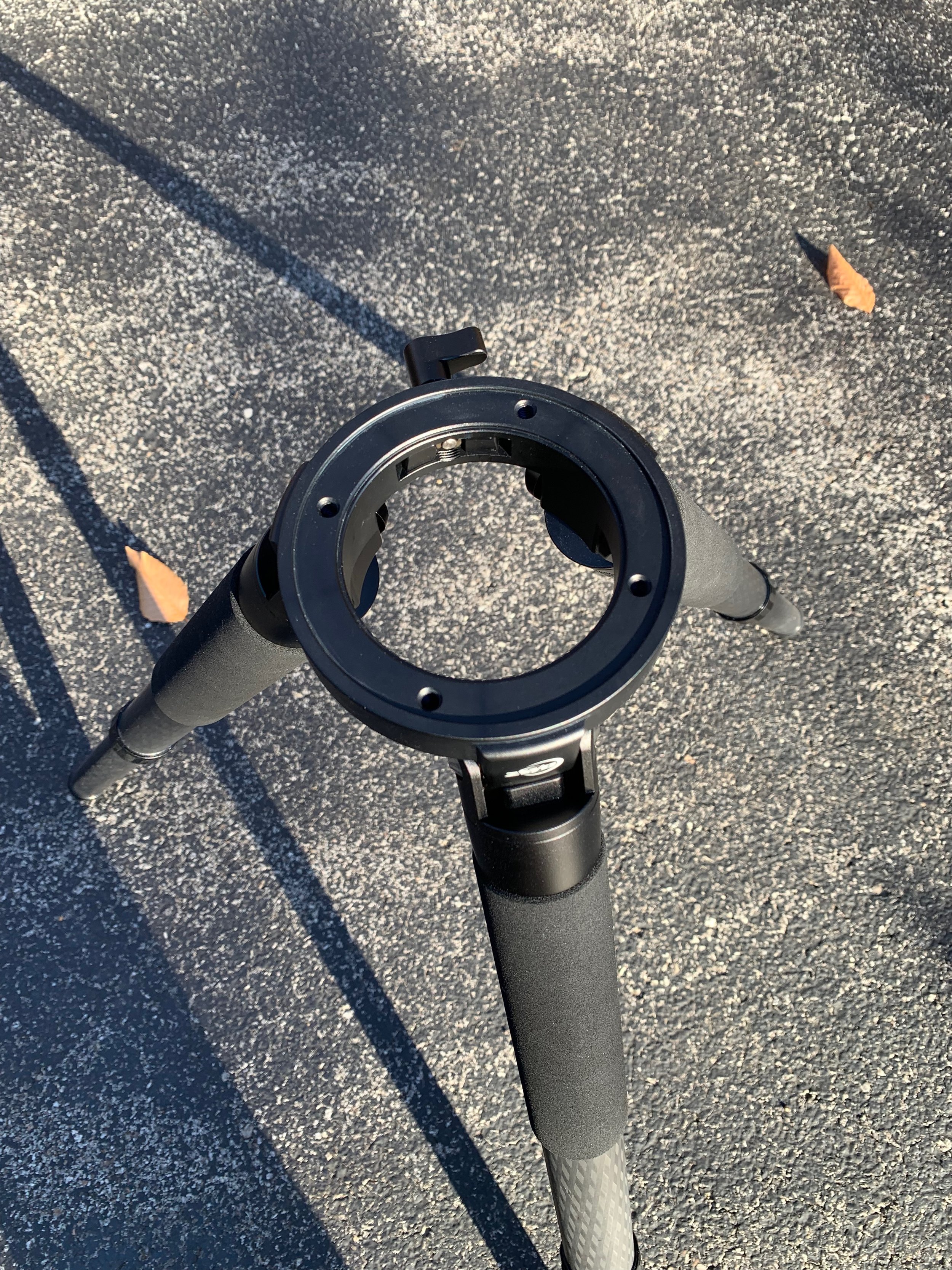
Looking down on the tripod with the extension removed.

The 160mm extension.
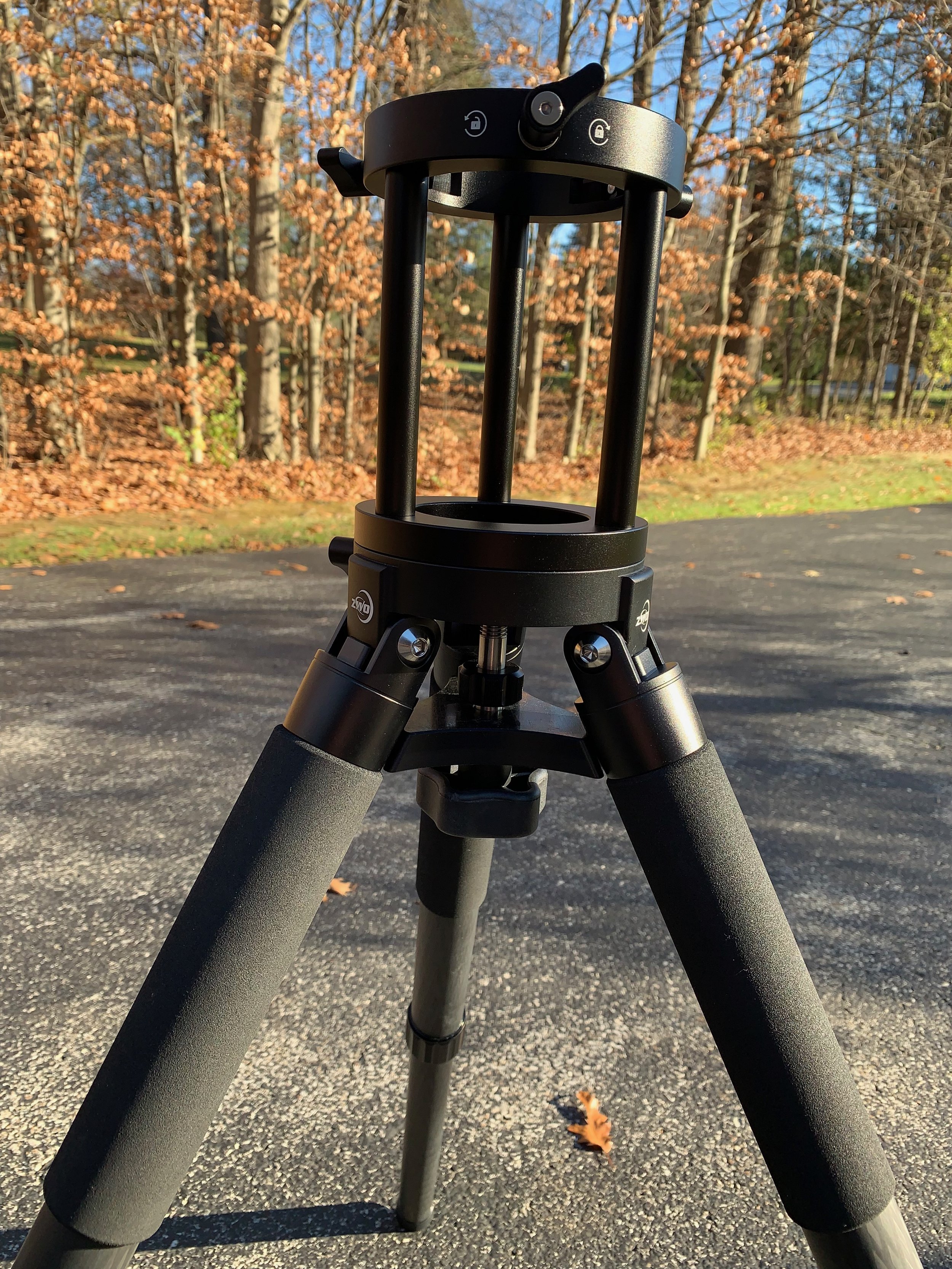
The tripod with extension mounted.
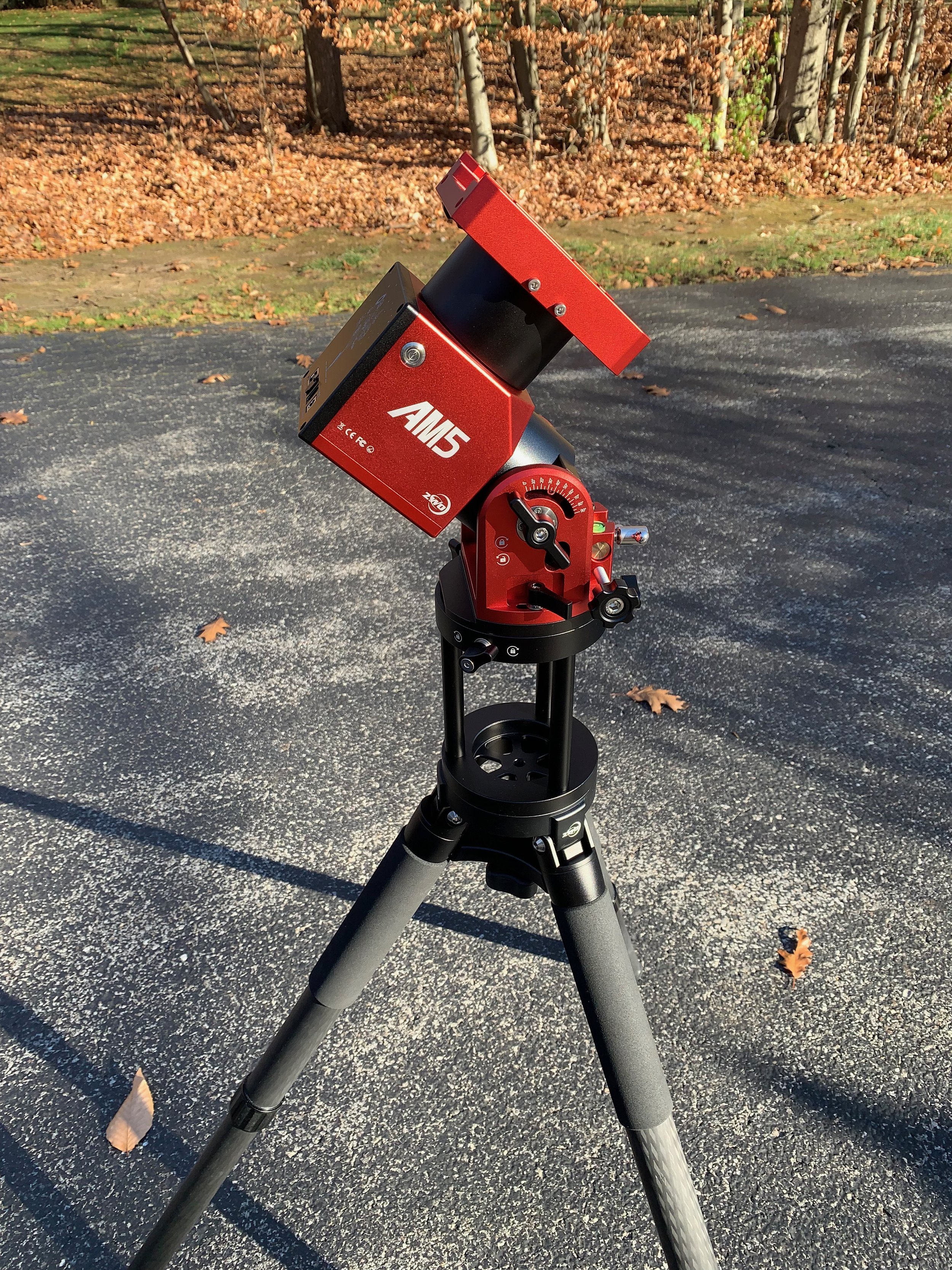
The entire assembly.
For the Polar Alignment camera, I decided to mount the camera on the bottom rail of the OTA with a bracket and mount a Polemaster PA camera on that.

The Polemaster Mounting Bracket (link to Amazon)

The Polemaster Camera (link to AgenaAstro)
Putting It All Together
Mounting the OTA on the AM5 was very simple. I just detached some key cables and removed the scope, and then clamped it onto the vixen mounting bracket of the AM5.
I then went about reconnecting the cables. When I was done - it was clear that I still had some cable management to do. I spent an hour one afternoon doing that and ended up with the following configuration:
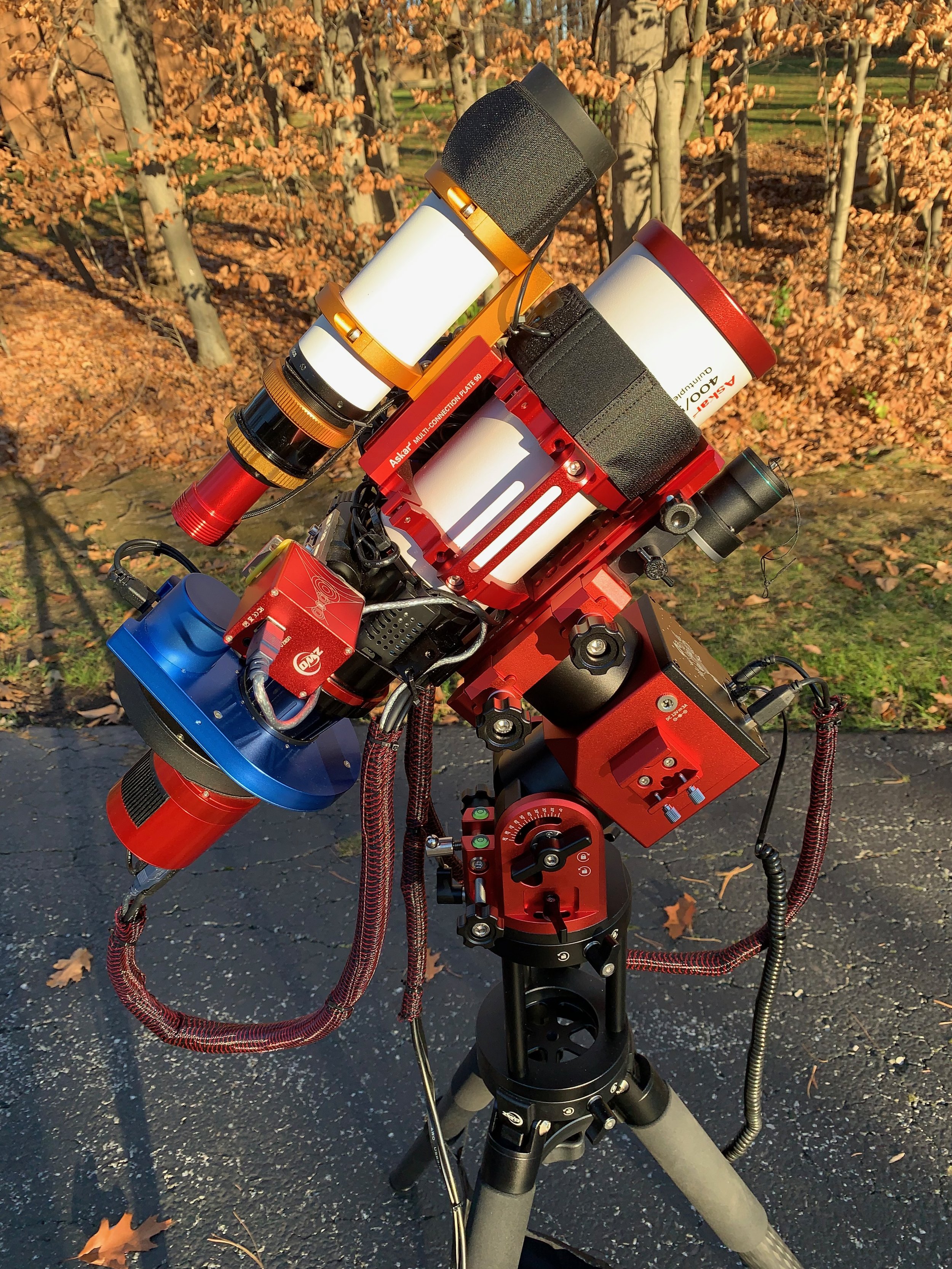
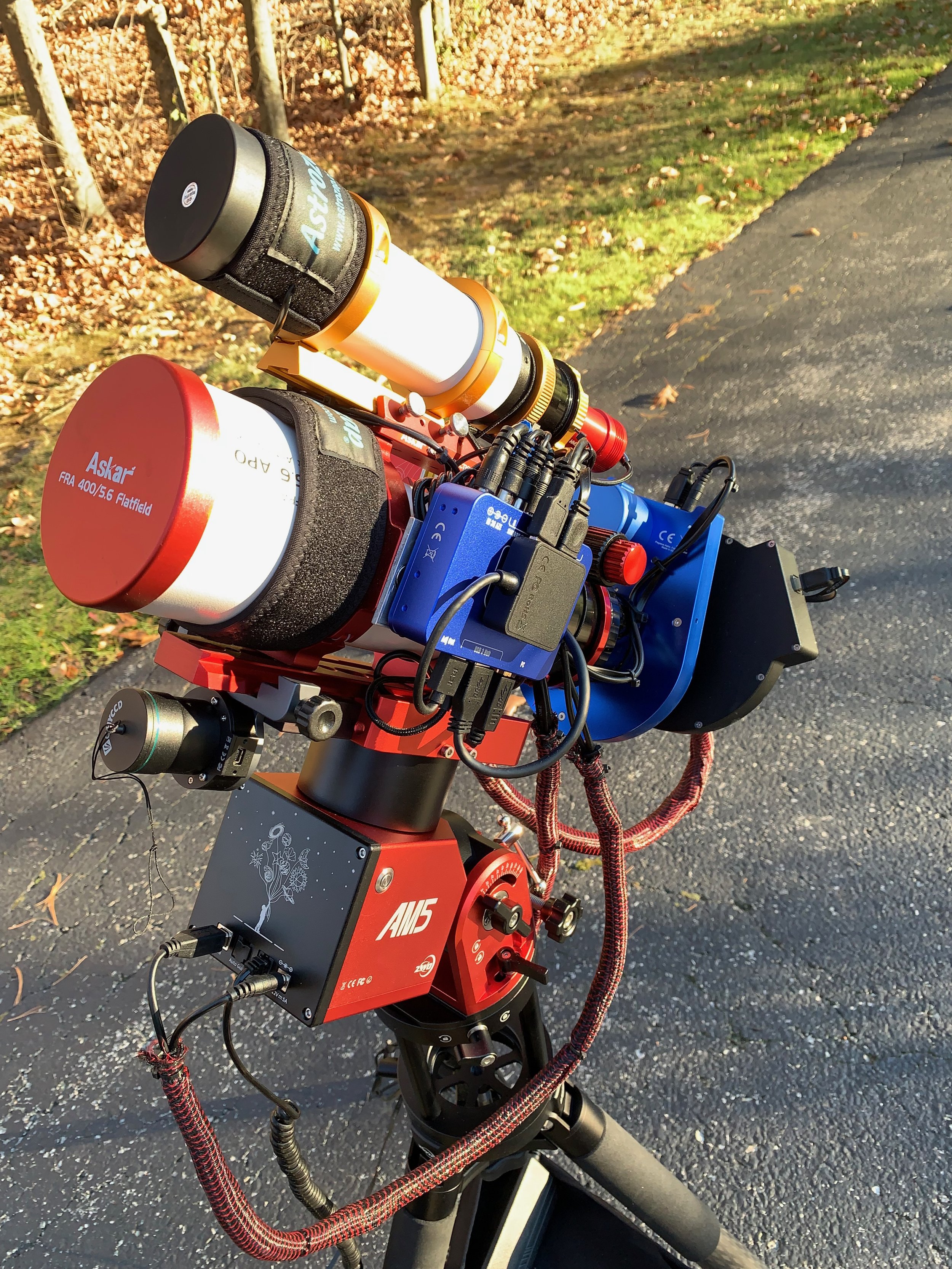

You can see how I mounted the Polemaster camera here:

The mounted Polemaster PA Camera
The New AM5 mount is ready for testing!
Software Configuration
The physical configuration was straightforward - now, I needed to change the software on the laptop that would be used to control the capture operations.
ASCOM Driver: I downloaded the current ASCOM driver from ZWO and installed it.
PHY Polemaster Software: I installed the latest version of PoleMaster app.
At his point, I was ready to get under the night sky and finish the setup. I had a clear night on Nov 23rd and planned and using this night to test out the new mount. But first, I had to finish the configuration.
So I took the rig out onto the driveway and went through the following steps:
Leveling the Mount: I leveled the mount using the bubble levels at the back of the mount.
Polar Alignment: I then ran Polemaster, following its directions for doing the first Polar Alignment ever on this mount. The ALT/Azimuth adjusters on the back of the mount made this very easy to do.

The Alt-Azimuth Adjusters and bubble levels.
PHD2 setup: At this point, it was time to set up PHD2. To do this, I created a new equipment profile for the mount. As part of this process, I usually set up the guiding algorithms. I typically use PEC Predictive on my mounts, but that did not seem like a good idea for this harmonic mount as the mount does not have the typical PEC profile you would get with a worm gear. Included with the mount was a sheet of paper that documented the Periodic Error from my particular mount. You can see that below:
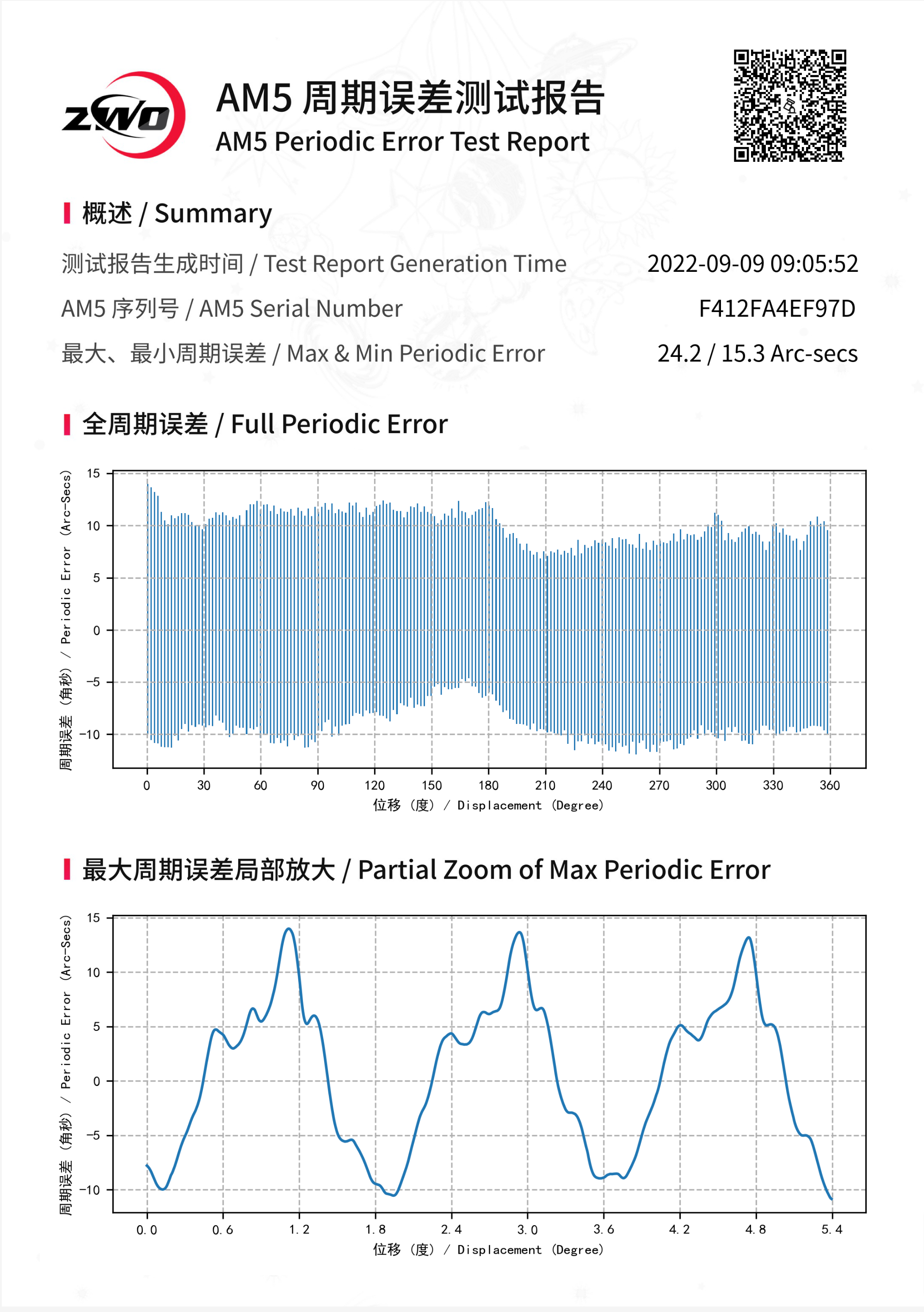
This chart shows the angle of rotation (0-360 degrees) on the bottom axis and the periodic error on the vertical access. The bar shown at each angular location represents the minimum and maximum error seen at that position on the mount. This is a range, not a value - so the performance here is not typical of a normal PEC curve, so I don’t think that would work. Instead, I set the algorithm to Hysteresis for Ra and Resist Switch - with FastSwitch enabled for Dec.
ZWO has a posting on things to know about this chart:
At this point, I did a calibration and then ran Guide Assistant to tweak the parameters.
I understood that this kind of drive would perform very well for astrophotography - but it needs active guiding to achieve this. Furthermore, the guiding exposure needs to be fairly short to react to the errors seen. To this end, I put the exposure at 1 second.
ZWO posted an interesting article on getting good guidance on the AM5. It seems to focus more on flex issues than things like PHD2 settings, but it is still an interesting read:
Sequence Generator Pro Set up: Next, I had to adapt my setup on SGP - which I use to control all of my sequences. I created a new Equipment profile and used most of the same parameters I had used in the past. One thing that had to change was my setup for meridian flips. With the IOptron CEM26, the mount would do a flip at some point past the meridian that you set. I then set up SGP to do a flip before this point. If there was a problem, I was confident that the mount would still do a flip even if SGP messed up. But the AM5 works differently. When it gets to the meridian - it just stops! So based on what I had read on various forums on the internet, I set up SGP to do a flip just before the meridian was hit.
With this done, I was ready to start my first sequence and see how things were doing.
Initial Results
The target for my first test was IC 1848 - The Soul Nebula. You can see the post for that Imaging Project HERE.
I started this project on the nights of Oct 21 and 22. But I still needed at least one more night of data collection to have a minimal set for processing. Little did I know when I started this project. that the last night of data collection would be done with the AM5 mount!
I began my sequence and let things run for a bit. As I looked at the RMS errors shown on PHD2, I was taken aback - I saw an error of 0.38 seconds! This is the lowest tracking error I had ever seen - therefore, I was skeptical. Surely it could not be doing this well? Something must be going wrong somewhere - right?
But as the exposure continued, my error remained quite low. After three hours, I think it went up a bit to about 0.4 - but I was delighted with the results I was getting! I looked at the subs coming in, and I saw beautiful round and tight stars!
The tracking error from the CEM 26 was much worse - typically over 1.0 seconds and often as high as 1.8! Subs from the CEM 26 Mount showed elongated stars.
Below are plots from the PHD2 guide logs for both the CEM26 and the AM5. Both have about the same vertical scale, so they are comparable.

A segment of the guide log for when the CEM26 mount was used.

A segment of the guide log when the AM5 mount was used.
Conclusion
I am very happy with the early results of my new ZWO AM5 mount! I have only had I one evening of data capture with it so far, so I am sure I will have more learnings as I work with it more. I will update this posting as I have new learnings!
The Final Version 2.0 Configuration:
Scope: Askar FRA400 72mm f/5. 6 Quintuplet Air-Spaced Astrograph
Focus Motor: ZWO EAF 5V
Guide Scope: William Optics 50mm guide scope
Guide Scope Rings: William Optics 50mm slide-base Clamping Ring Set
Mount: ZWO AM5 - New!
Tripod: ZWO TC40 Carbon Fiber tripod with 160mm Extention - New!
Camera: ZWO ASI1600MM-Pro
Camera Rotator: Pegasus Astro Falcon Camera Rotator
Filter Wheel: ZWO EFW 1.2 5x8
Filters: ZWO 1.25” LRGB Gen II, Astronomiks 6nm Ha, OIII,SII
Guide Camera: ZWO ASI290MM-Mini
Dew Strips: Dew-Not Heater strips for Main and Guide Scopes
Power Dist: Pegasus Astro Powerbox Advanced
USB Dist: Pegasus Astro Powerbox Advanced
Polar Alignment
Cam: PoleMaster